Vertically aligned liquid crystal display
a liquid crystal display and vertical alignment technology, applied in non-linear optics, instruments, optics, etc., can solve problems such as light leakage, and achieve the effect of minimizing light leakage and high contras
- Summary
- Abstract
- Description
- Claims
- Application Information
AI Technical Summary
Benefits of technology
Problems solved by technology
Method used
Image
Examples
embodiment 1
[0067]Configuration of the First VA-LCD
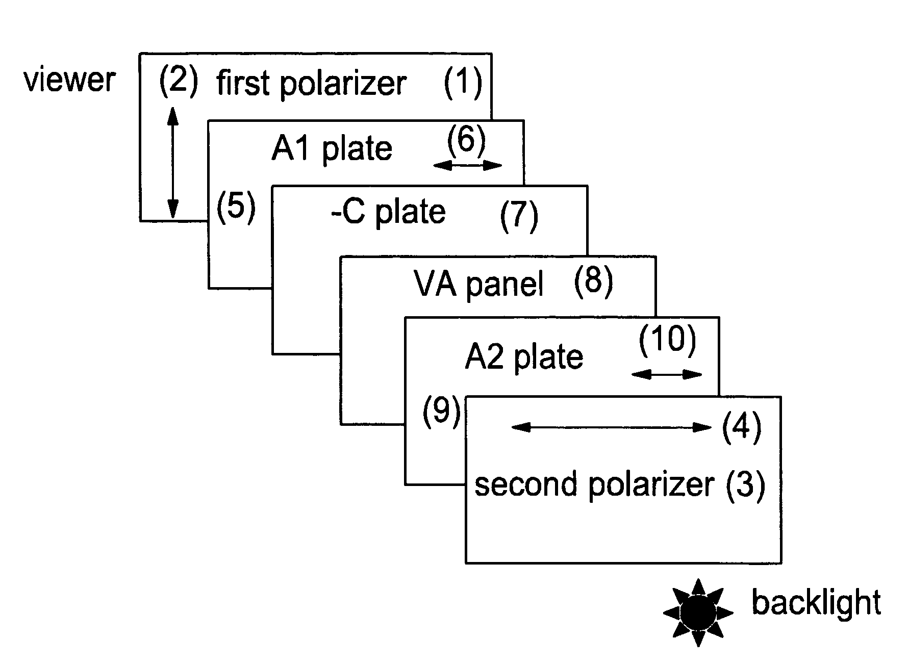
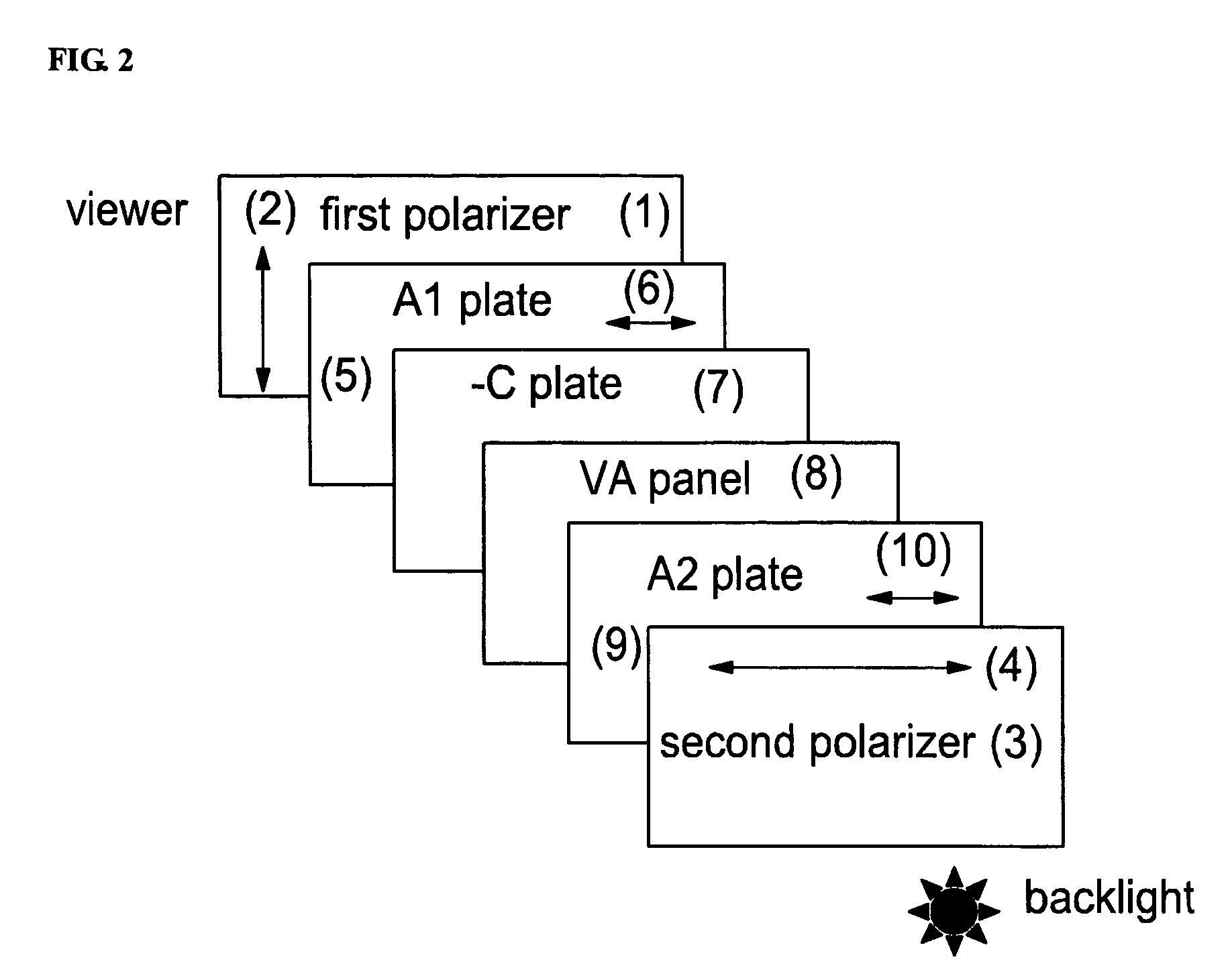
[0068]Referring to FIG. 2, a VA-panel comprises a plurality of VA liquid crystal cells 8 having a cell gap of 2.9 μm where the liquid crystal cell is filled with liquid crystals having a pre-title angle of 90 degrees, a dielectric anisotropy Δ∈ is −4.9, and a birefringence Δn is 0.099. The −C plate 7 is made of a liquid crystal film, and has a thickness retardation value Rth of −240 nm for a wavelength of 550 nm. The A1 plate 5 being close to the first polarizer 1 has an in-plane retardation value Rin of 90 nm, and the A2 plate 9 being close to the second polarizer 3 has an in-plane retardation value Rin of 340 nm. The inner protective films of the first polarizer 1 and the second polarizer 3 are made of triacetate cellulose film with a thickness of 40 μm and a thickness retardation value of −28 nm.
[0069]When using white light, contrast characteristics over 0 to 80 degrees with respect to all azimuth angles is shown in FIG. 6. In FIG. 6, the ce...
embodiment 2
[0071]Configuration of Second VA-LCD
[0072]Referring to FIG. 3, a VA-panel comprises a plurality of liquid crystal cells 8 filled with liquid crystals with a cell gap of 2.9 μm, a pre-title angle of 90 degrees, a dielectric anisotropy Δ∈ is −4.9, and a birefringence Δn is 0.099. The −C plate 7 is made of a liquid crystal film, has a thickness retardation value Rth of −180 nm for a wavelength of 550 nm. The A1 plate 5 being close to the first polarizer 1 has an in-plane retardation value Rin of 120 nm, and the A2 plate 9 being close to the second polarizer 3 has an in-plane retardation value Rin of 80 nm. The inner protective films of the first polarizer 1 and the second polarizer 3 are made of TAC film with a thickness of 80 μm and a thickness retardation value of −56 nm.
[0073]When using white light, contrast characteristics over 0 to 80 degrees with respect to all azimuth angles are shown in FIG. 7. In FIG. 7, the contrast characteristic over 0 to 80 degrees with respect to all azim...
embodiment 3
[0074]Configuration of Third VA-LCD
[0075]Referring to FIG. 4, a VA-panel comprises a plurality of liquid crystal cells 8 filled with liquid crystals with a cell gap of 2.9 μm, a pre-title angle of 90 degrees, a dielectric anisotropy Δ∈ is −4.9, and a birefringence Δn is 0.099.
[0076]The bi-axial retardation film 11 being close to the first polarizer 1 has an in-plane retardation value Rin of 70 nm and a thickness retardation value, Rth of −140 nm. The +A plate 9 being close to the second polarizer 3 has an in-plane retardation value Rin of 30 nm. The inner protective film of the first polarizer 1 is made of a TAC film with a thickness of 40 μm and its thickness retardation value is −28 nm. The inner protective film of the second polarizer 3 is made of TAC film and has a thickness of 80 μm and a thickness retardation value of −56 nm.
[0077]When using white light, contrast characteristics over 0 to 80 degrees with respect to all azimuth angles is shown in FIG. 8.
[0078]In FIG. 8, the con...
PUM
| Property | Measurement | Unit |
|---|---|---|
| thickness retardation | aaaaa | aaaaa |
| wavelength | aaaaa | aaaaa |
| wavelength | aaaaa | aaaaa |
Abstract
Description
Claims
Application Information
 - R&D
- Intellectual Property
- Life Sciences
- Materials
- Tech Scout
- Unparalleled Data Quality
- Higher Quality Content
- 60% Fewer Hallucinations
Browse by: Latest US Patents, China's latest patents, Technical Efficacy Thesaurus, Application Domain, Technology Topic, Popular Technical Reports.
© 2025 PatSnap. All rights reserved.Legal|Privacy policy|Modern Slavery Act Transparency Statement|Sitemap|About US| Contact US: help@patsnap.com


