Optical lens, compound lens and method for producing the same, as well as cemented lens and method for producing the same

a technology of optical lenses and cemented lenses, applied in the field of optical lenses and compound lenses, can solve problems such as transmission eccentricity, and achieve the effect of suppressing transmission eccentricity and less susceptible to deformation or chipping

Inactive Publication Date: 2009-01-06
HUIZHOU DAYAWAY EVER BRIGHT ELECTRONICS IND CO LTD +2
View PDF4 Cites 17 Cited by
  • Summary
  • Abstract
  • Description
  • Claims
  • Application Information

AI Technical Summary

Benefits of technology

[0013]The present invention has been devised in view of the aforementioned problems. An object of the present invention is to provide an optical lens which is less susceptible to deformation or chipping and suppresses transmission eccentricity, a compound lens and a method for producing the same, as well as a cemented lens and a method for producing the same.

Problems solved by technology

This axial misalignment causes a problem of transmission eccentricity.

Method used


Image

  • Optical lens, compound lens and method for producing the same, as well as cemented lens and method for producing the same
  • Optical lens, compound lens and method for producing the same, as well as cemented lens and method for producing the same
  • Optical lens, compound lens and method for producing the same, as well as cemented lens and method for producing the same

Examples


Embodiment Construction

[0051]With reference to the drawings, hereinafter, description will be given of preferred embodiments of the present invention.

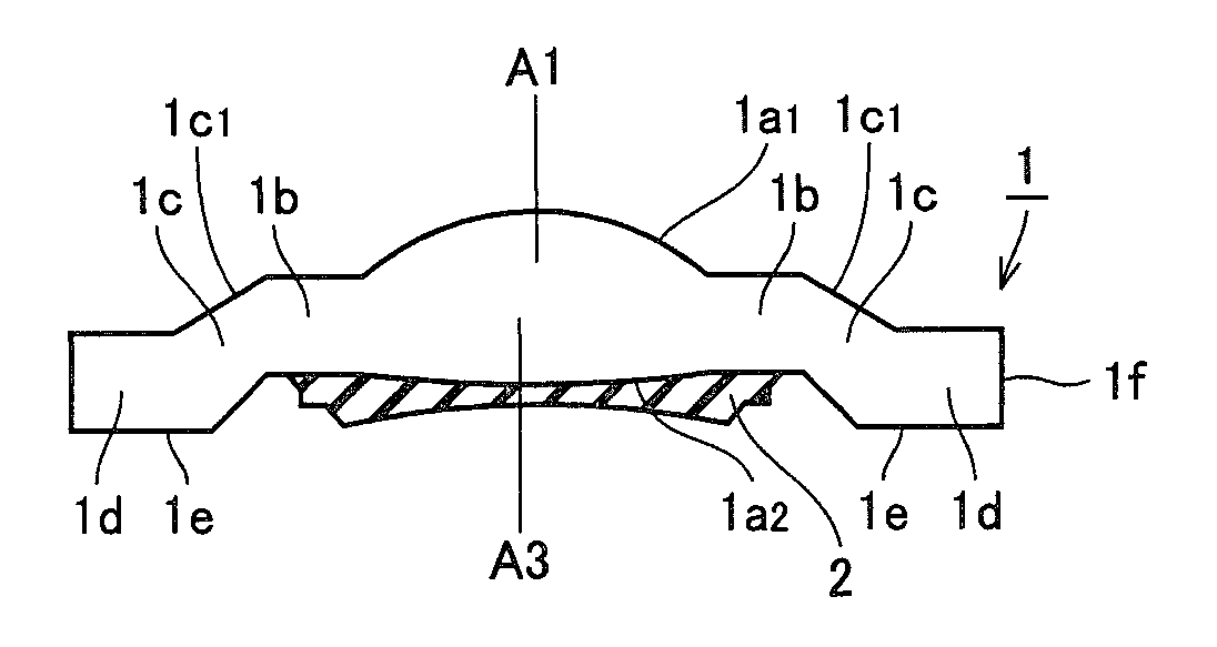
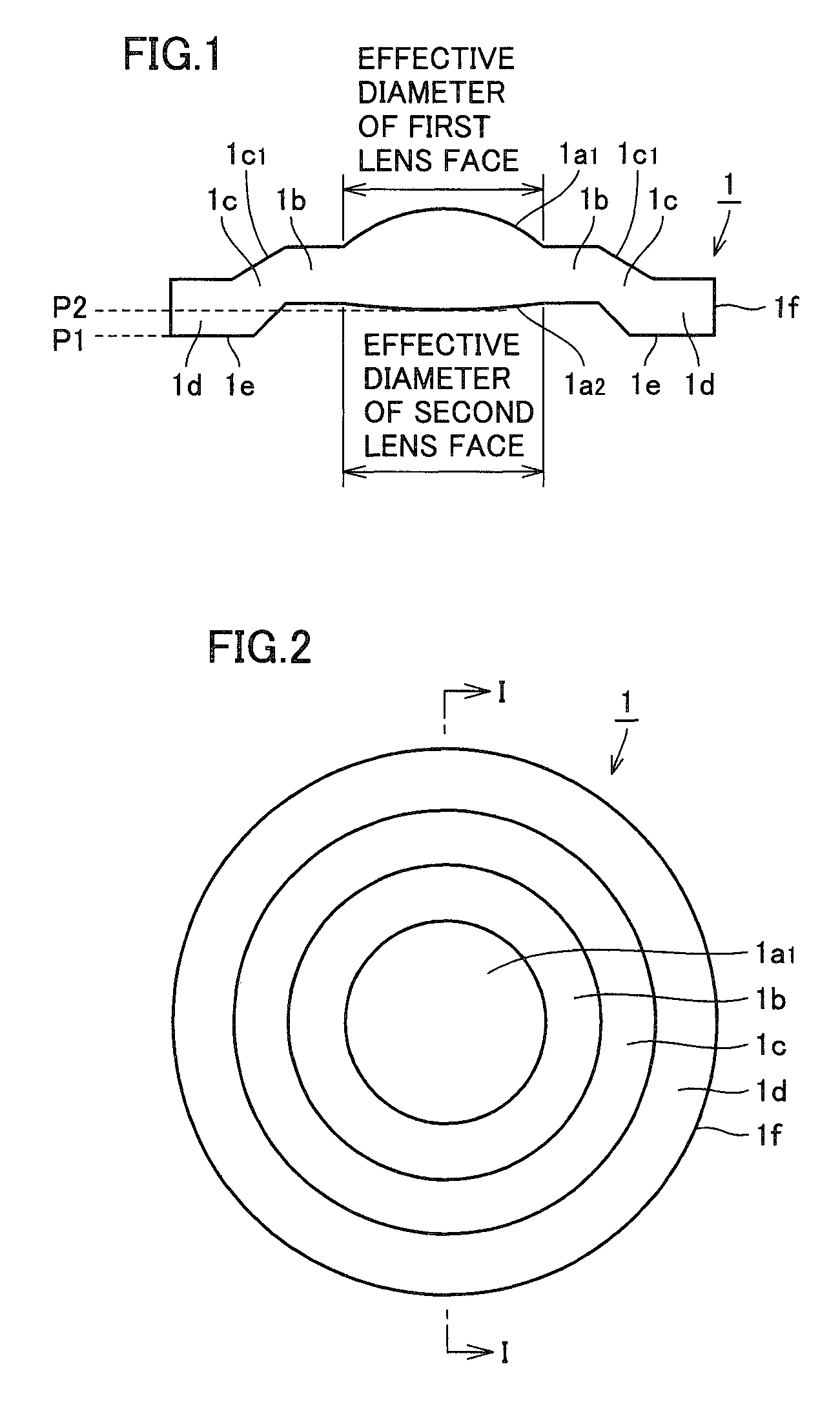
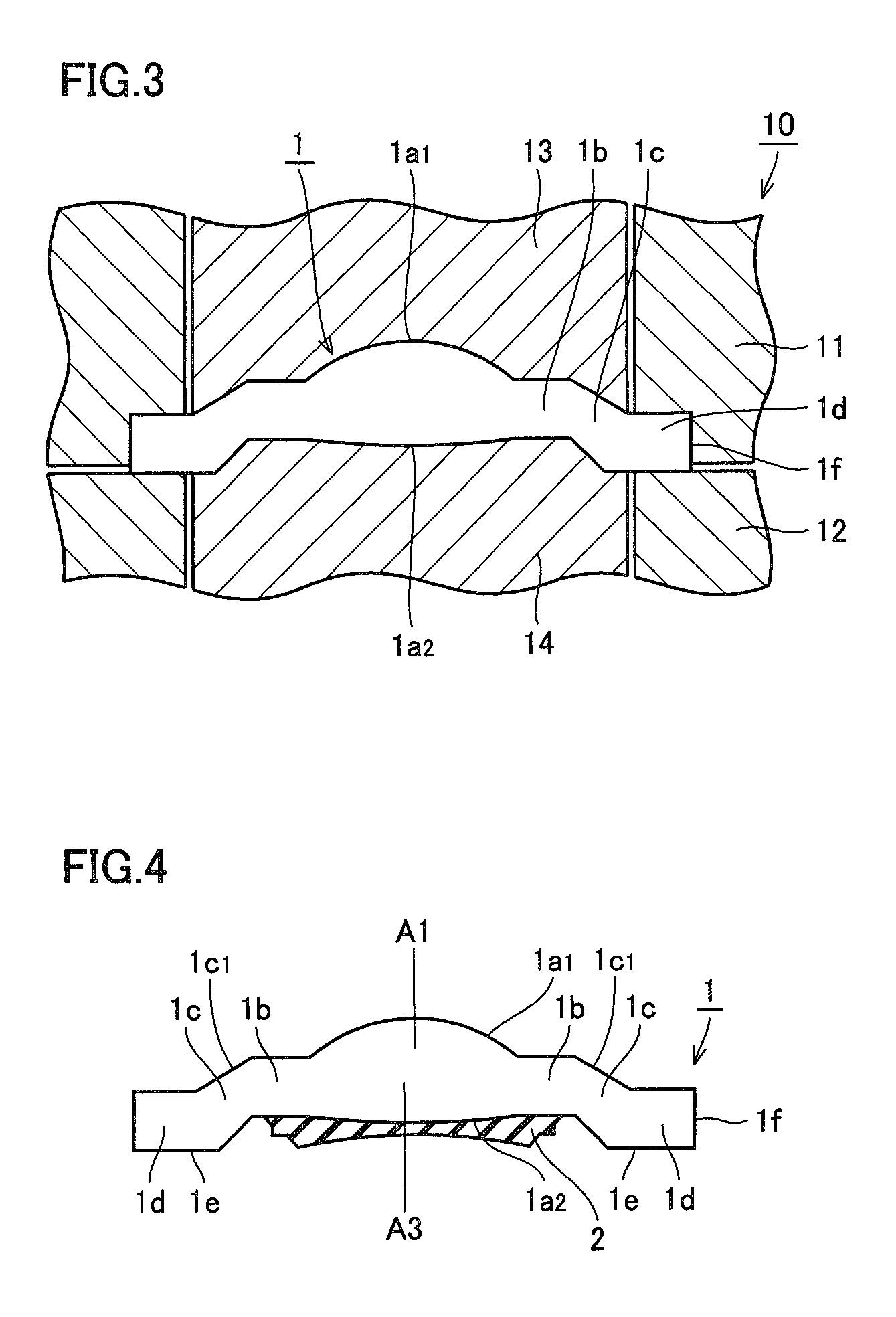
[0052]With reference to FIGS. 1 and 2, an optical lens 1 according to one embodiment of the present invention is made of a plastic material or a glass material, for example. Optical lens 1 includes a lens effective portion (an optical functional portion), a flat portion 1b located at an outer periphery of the lens effective portion, an inclined portion 1c located at an outer periphery of flat portion 1b, and a flange portion 1d located at an outer periphery of inclined portion 1c. The lens effective portion has, on a first side (an upper side in FIG. 1), a first lens face 1a1 with a first radius of curvature and also has, on a second side (a lower side in FIG. 1), a second lens face 1a2 with a second radius of curvature larger than the first radius of curvature. Herein, second lens face 1a2 may have no curvature. In the embodiment, each of first lens face 1a...


PUM

PropertyMeasurementUnit
radius of curvatureaaaaaaaaaa
diameteraaaaaaaaaa
transmission eccentricityaaaaaaaaaa

Abstract

An optical lens includes a lens effective portion, an inclined portion and a flange portion. The lens effective portion has, on a first side, a lens face with a small radius of curvature and also has, on a second side, a lens face with a large radius of curvature. The inclined portion has, on the first side, an inclined face inclined outwardly from the first side to the second side. The flange portion has, on the second side, a reference face protruding longer than the lens face with the large radius of curvature on the second side. Thus, it is possible to obtain an optical lens which is less susceptible to deformation or chipping and suppresses transmission eccentricity, a compound lens and a method for producing the same, as well as a cemented lens and a method for producing the same.

Description

BACKGROUND OF THE INVENTION[0001]1. Field of the Invention[0002]The present invention relates to an optical lens, a compound lens and a method for producing the same, as well as a cemented lens and a method for producing the same.[0003]2. Description of the Background Art[0004]As an optical device becomes more sophisticated in functionality, recently, various lenses have been required as a lens for use in an optical system of such an optical device (refer to Japanese Patent Laying Open Nos. 2002-144203, 07-117143, 2002-286987 and 2005-062432). In order to fill the need, a compound lens has been used as the lens. The compound lens has a configuration that a certain lens is cemented to a matrix lens. For example, the compound lens is an aspherical lens having a configuration that a resin lens is cemented to a surface of a spherical lens.[0005]FIG. 26 is a schematic sectional view showing a configuration of a conventional compound lens. With reference to FIG. 26, the compound lens incl...

Claims


Application Information

Patent Timeline
Patent Type & Authority Patents(United States)
IPC IPC(8): G02B3/08G02B13/18G02B3/02
CPCG02B7/02G02B1/04G02B3/02
Inventor UETA, YUTAKANAKAGAWA, YOUHEI
Owner HUIZHOU DAYAWAY EVER BRIGHT ELECTRONICS IND CO LTD
Why Eureka
Try Eureka