
Fuel injection control device for a variable-fuel engine and engine incorporating same

a control device and variable fuel technology, applied in the direction of electrical control, process and machine control, instruments, etc., can solve the problem of narrow adjustment range of fuel injection quantity with respect to alcohol concentration, and achieve the effect of reducing the cost of the fuel engine fuel injection control device, ensuring stability at the time of idle, and enhancing respons

Active Publication Date: 2009-01-13
HONDA MOTOR CO LTD
View PDF13 Cites 22 Cited by
  • Summary
  • Abstract
  • Description
  • Claims
  • Application Information

AI Technical Summary

Benefits of technology

[0017]By constituting the fuel injection control apparatus for a variable-fuel engine according to the first and second aspects of the present invention in the above-mentioned manner, the basic fuel injection time can be changed corresponding to the concentration of alcohol contained in the fuel and hence, an adjustment range of the fuel injection quantity with respect to the concentration of alcohol is broadened whereby even when the concentration of alcohol contained in the fuel is changed, the engine can be operated in a stable manner. Particularly, according to the fuel injection control apparatus for a variable-fuel engine of the second aspect of the present invention, the concentration of alcohol contained in the fuel can be estimated based on the air-fuel ratio correction coefficient and hence, it is unnecessary to provide the alcohol concentration sensor in the inside of the fuel tank thus achieving the reduction of a cost of the fuel engine fuel injection control device.
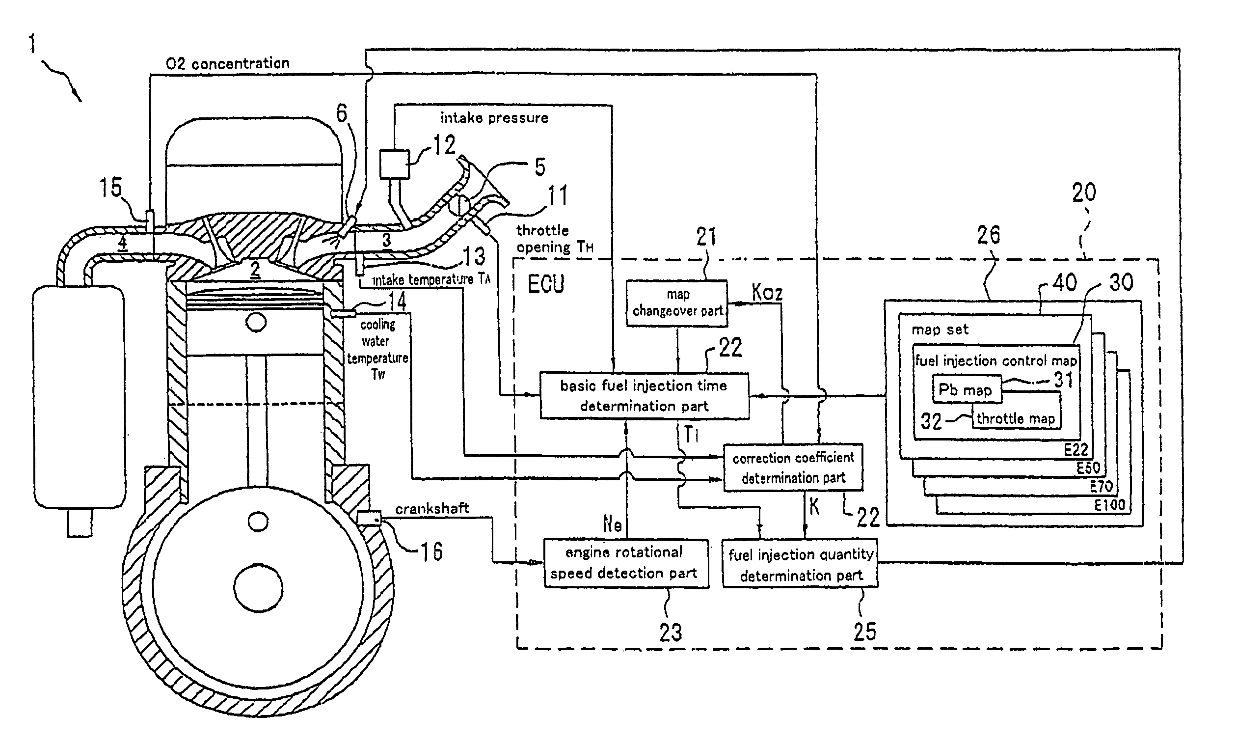
[0018]Here, by constituting the fuel injection control apparatus for a variable-fuel engine such that the basic fuel injection time can be determined based on the intake pressure and the engine rotary speed, it is particularly possible to stabilize the engine rotary speed in the vicinity of the idling rotation. Further, by providing the set consisting of the fuel injection control map which determines the basic fuel injection time based on the intake pressure and the engine rotary speed and the fuel injection control map which determines the basic fuel injection time based on the throttle opening and the engine rotary speed and by changing over these maps in response to the state of the engine, it is possible to ensure the stability at the time of idling and to enhance the response at the time of a high load.
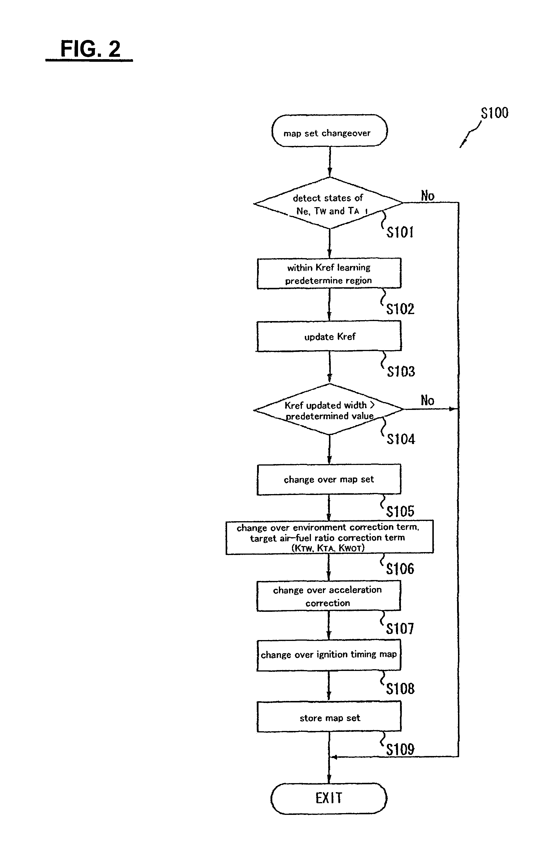
[0019]Here, by storing the environment correction coefficient table based on the intake temperature, the atmospheric pressure, the engine cooling water temperature and the like corresponding to at least three or more concentrations of alcohol or the map set which can obtain the favorable operation performance by changing over the acceleration correction, it is possible to operate the engine with the map set which stores the operation of the engine as it is until the next starting and a changeover control of the map set is performed and the maps on the environment correction coefficient, acceleration correction and the ignition timing.

Problems solved by technology

Accordingly, even when the concentration of alcohol in the fuel is changed, the basic fuel injection time is the value which is preliminarily set with respect to the engine rotary speed and the intake pressure and hence, there has been a drawback that an adjustment range of a fuel injection quantity with respect to the concentration of alcohol is narrow.

Method used


Image

  • Fuel injection control device for a variable-fuel engine and engine incorporating same
  • Fuel injection control device for a variable-fuel engine and engine incorporating same
  • Fuel injection control device for a variable-fuel engine and engine incorporating same

Examples


Embodiment Construction

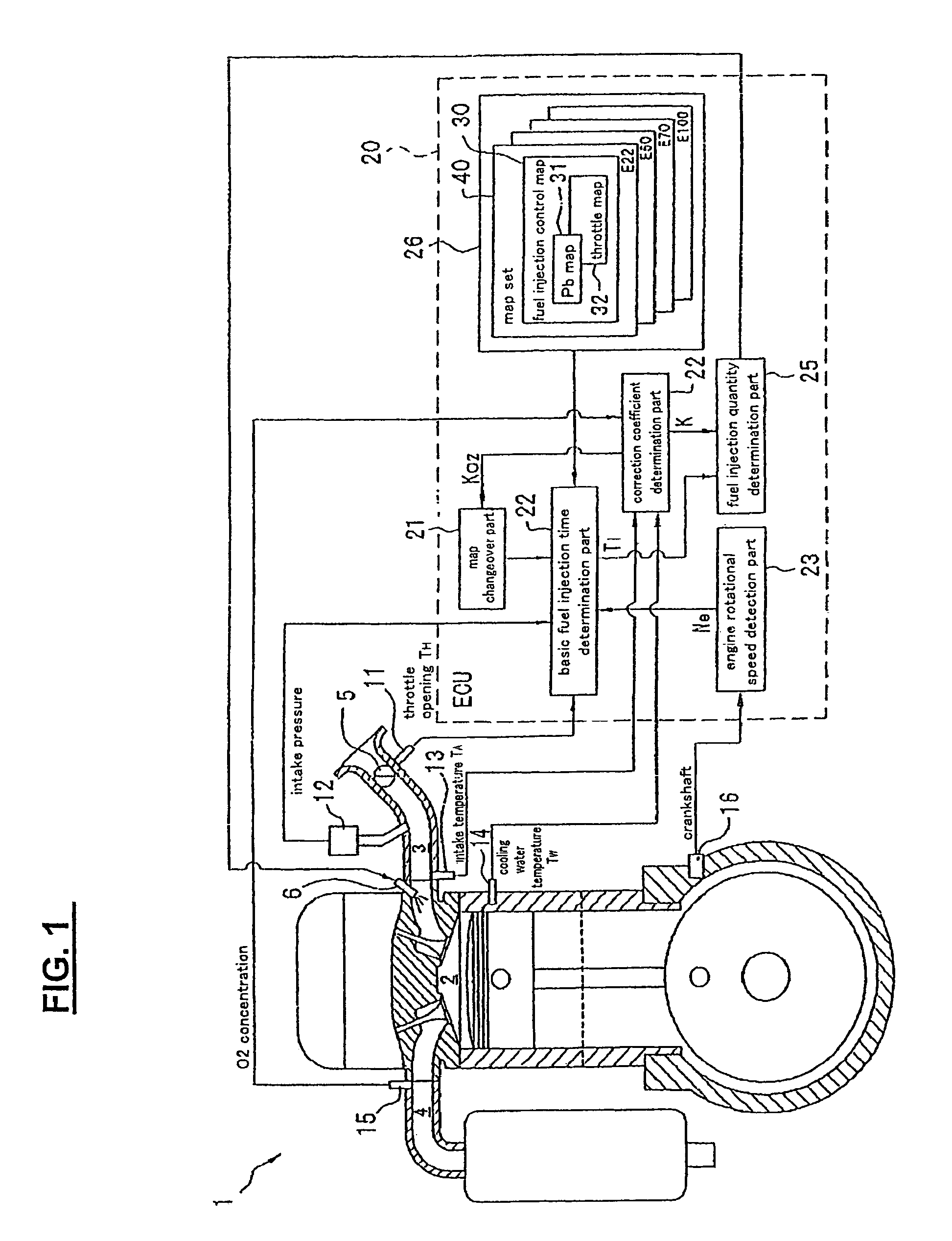
[0027]Hereinafter, a preferred embodiment of the present invention is explained in conjunction with drawings. In FIG. 1, an engine 1 includes an intake pipe 3 and an exhaust pipe 4 which are communicated with a combustion chamber 2. A throttle valve 5 which adjusts a quantity of intake air and an injector 6 which injects fuel are mounted on the intake pipe 3. Further, the engine 1 mounts a throttle opening sensor 11 which detects the opening of the throttle valve 5, an intake pipe absolute pressure sensor 12 which detects a pressure (an intake pressure) in the inside of the intake pipe 3, an intake temperature sensor 13 which detects a temperature of air which flows in the combustion chamber 2 through the intake pipe 3 (intake temperature), a water temperature sensor 14 which detects a temperature of cooling water which flows in a water jacket formed in a cylinder head and a cylinder block of the engine 1 and cools these parts (water temperature), an O2 sensor 15 which is mounted on...


PUM


Abstract

A fuel injection control apparatus, for a variable-fuel engine, includes a plurality of stored maps for determining a basic fuel injection time corresponding to a state of an engine and alcohol concentration in the fuel. The apparatus includes a memory storage region which stores the fuel injection control maps. The apparatus also includes an oxygen sensor disposed in an exhaust pipe for detecting oxygen concentration in an exhaust gas; a basic fuel injection time calculator which determines the basic fuel injection time using the currently selected fuel injection control map; a correction coefficient calculator which determines an air-fuel ratio correction coefficient for correcting the basic fuel injection time; a fuel injection quantity calculator; and a map changeover part which selects the fuel injection control map of the concentration of alcohol close to the concentration of alcohol of the fuel based on the air-fuel ratio correction coefficient.

Description

CROSS-REFERENCE TO RELATED APPLICATIONS[0001]The present application claims priority under 35 USC §119 based on Japanese patent application No. 2006-259501, filed on Sep. 25, 2006. The entire subject matter of this priority document is herein incorporated by reference.BACKGROUND OF THE INVENTION[0002]1. Field of the Invention[0003]The present invention relates to a fuel injection control device used in a variable-fuel engine which can be operated with an essentially pure alcohol fuel, with a fuel produced by mixing gasoline and alcohol in a variable ratio, or with normal gasoline fuel.[0004]2. Description of the Background Art[0005]Recently, there has been developed an FFV (Flexible Fuel Vehicle) which mounts a variable-fuel engine thereon, wherein the variable-fuel engine is operable either with essentially pure alcohol (ethanol) fuel, with a fuel which is produced by mixing gasoline and alcohol in a variable ratio, or with normal gasoline as a fuel.[0006]Due to the difference in a...

Claims


Application Information

Patent Timeline
Patent Type & Authority Patents(United States)
IPC IPC(8): F02D41/30
CPCF02D41/0025F02D41/1454F02D41/2422F02D41/2454F02D19/084F02D19/088F02D41/062F02D2200/0612Y02T10/36Y02T10/30
Inventor KOKUBU, SHIRO
Owner HONDA MOTOR CO LTD
Learn More