Automatic retractable safety syringe

a safety syringe and automatic retractable technology, which is applied in the field of disposable hypodermic syringes, can solve the problems of occupying space for the locking mechanism, reducing the safety of the syringe, so as to prevent the use of accidental needle pricks, prevent or reduce injuries, and reduce the cross section of the plunger.

Active Publication Date: 2009-01-13
REVOLUTIONS MEDICAL CORP +1
View PDF11 Cites 4 Cited by
  • Summary
  • Abstract
  • Description
  • Claims
  • Application Information

AI Technical Summary

Benefits of technology

[0008]The present invention is directed to a safety syringe that retracts its needle into the syringe barrel to prevent the used from accidental needle prick. The retractable needle protects various people, including healthcare workers, their patients and sanitation workers involved with disposal of medical waste. The invention may prevent or reduce injuries ranging from minor skin lacerations to serious contamination by medications, germs or viruses. The syringe is preferably a disposable, single use device, and may be available in various sizes and shapes. A syringe according to this invention may also be used in non-medical applications, such as chemical handling processes and or in analytical applications.
[0009]A preferred embodiment includes a retractable needle assembly comprising a needle seat for supporting a hypodermic needle, and a generally tubular body which comprises the barrel and serves as a reservoir for injectable or withdrawn fluid. The barrel is open at both ends to receive a plunger at the plunger (proximal) end and a needle at the opposite (distal) end. A hollow plunger is slidably mounted within the barrel and extends from the plunger end for engagement by the user. A seal is provided between the plunger and barrel to prevent air from passing into or out of the barrel around the plunger and through the plunger end. A piston is slidably mounted within in the plunger such that movement of the plunger into the fill position locks the piston in place. A seal between the piston and the interior of the plunger prevents air or fluid from passing by the piston into the plunger. As the plunger is depressed to inject the fluid the plunger moves axially in the barrel while the piston is stationary. The relative axial movement of the plunger in relation to the piston causes a vacuum to be created within the plunger. The relatively smaller cross section of the plunger as compared to the barrel produces a corresponding greater vacuum force. The plunger in the fully depressed position releases the needle carrier from the end of the barrel and the vacuum pulls the needle carrier and needle into the hollow plunger.

Problems solved by technology

One disadvantage of the above syringes is that the locking mechanism takes up some space in the barrel of the syringe and may prevent all of the measured liquid from being ejected by the plunger.
This problem is exacerbated in the very small syringes such as the 1 cc tuberculin type.
In addition the narrowness of the barrel of the 1 cc syringe makes it difficult to design a needle carrier and locking mechanism that will fit in the barrel without enlarging the diameter so much as to make the calibration useless.
The main drawback to the second invention is that the entire barrel has to be evacuated and the force applied over the entire cross sectional area is relatively small.

Method used


Image

  • Automatic retractable safety syringe
  • Automatic retractable safety syringe
  • Automatic retractable safety syringe

Examples


Embodiment Construction

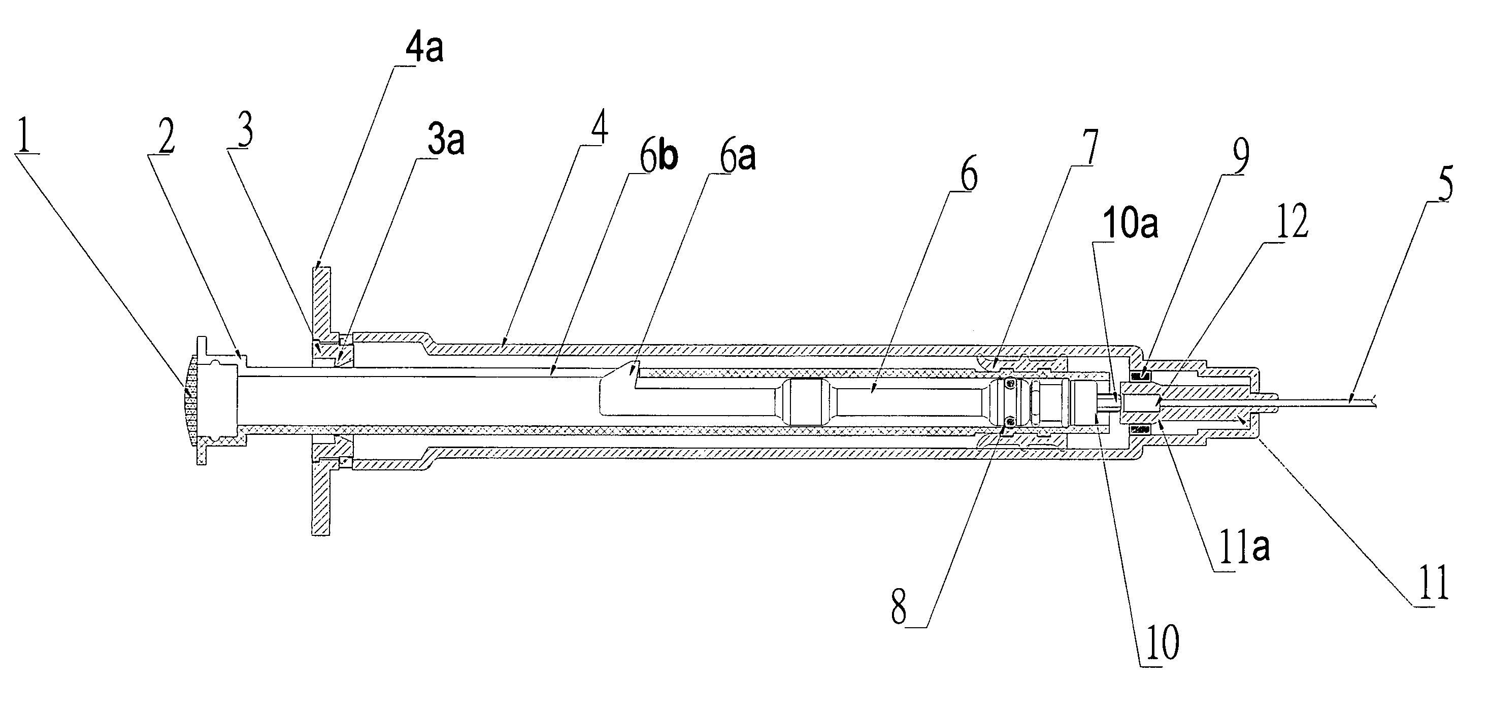
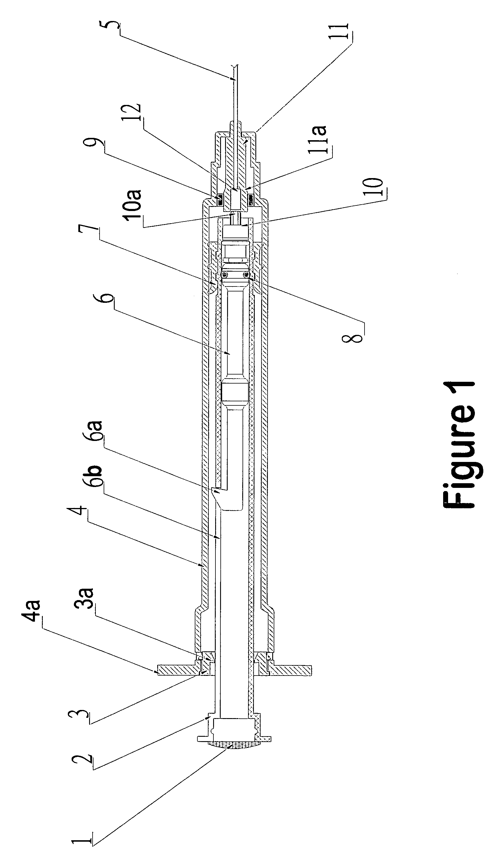
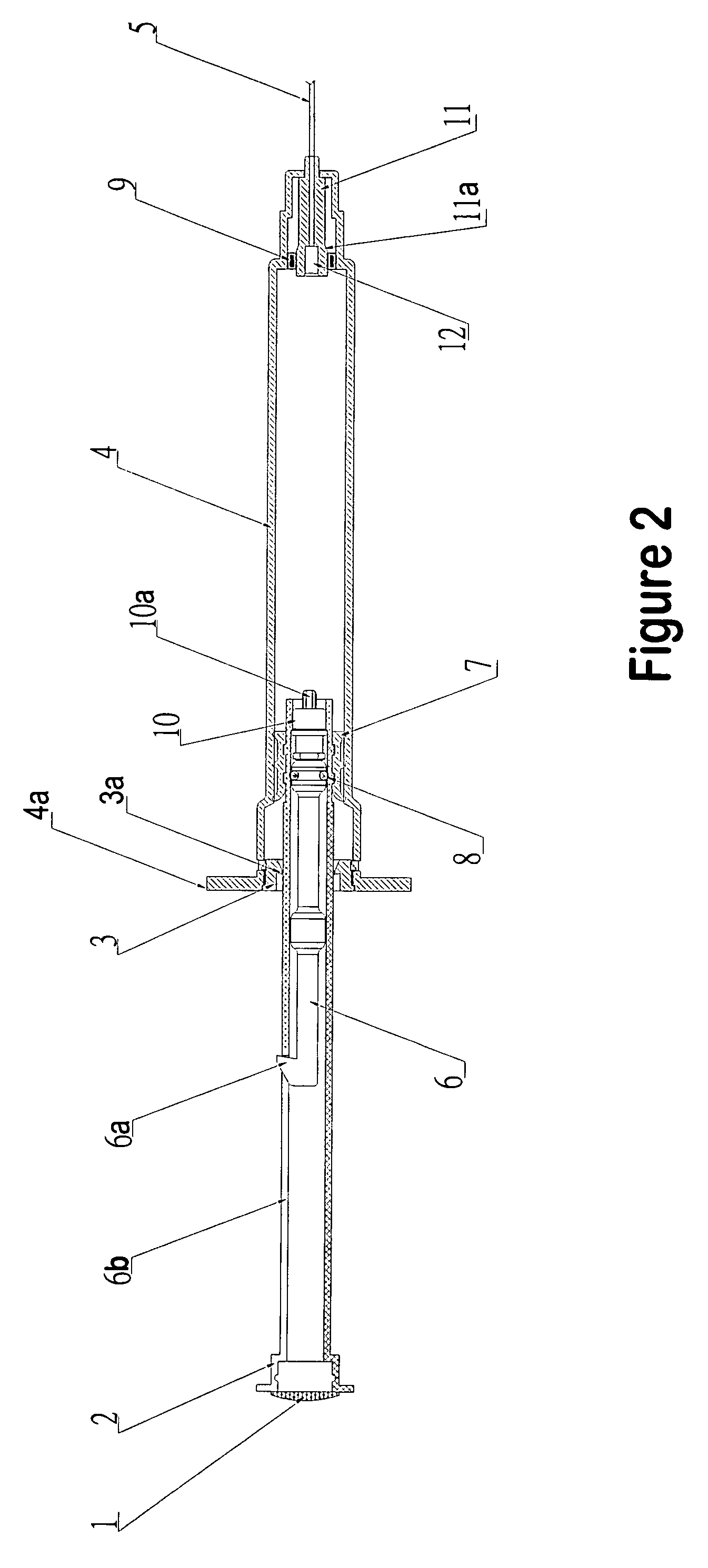
[0016]For a detailed description of the preferred embodiment the reader is directed to accompany FIGURES in which like components are given like reference numerals. There is shown a retractable needle syringe having a barrel 4 having finger flanges 4a at the proximal end and a hypodermic needle 5 mounted at the distal end. A hollow plunger 2 having a plunger cover 1 at the proximal end and a plunger seal 7 about the exterior of the distal end is slidably mounted within the barrel 4 with a plunger vacuum seal 10 releasably secured in the distal end. A barrel stopper 3 is secured at the proximal end of the barrel 4 to prevent air from entering the barrel at the proximal end around the plunger 2. A needle seat washer 9 surrounds the needle mounting 11 and retains the needle 5 and needle mounting 11 in the distal end of the barrel 4. A piston 6 is slidably mounted within the hollow plunger 2 having a piston vacuum seal 8 at the distal end and a piston lock 6a at the proximal end. A nipp...


PUM


Abstract

A syringe includes a retractable needle assembly comprising a needle seat, a hypodermic needle, and a barrel. A hollow plunger is slidably mounted within the barrel. A seal is provided between the plunger and barrel to prevent air from passing into or out of the barrel. A piston is slidably mounted within the plunger such that movement of the plunger into the fill position locks the piston in place. A seal between the piston and the interior of the plunger prevents air or fluid from passing into the plunger. As the plunger is depressed the plunger moves in the barrel while in the piston is stationary. The relative axial movement of the plunger in relation to the piston causes a vacuum to be created within the plunger. The plunger in the fully depressed position releases the needle carrier and the vacuum pulls the needle carrier and needle into the hollow plunger.

Description

BACKGROUND OF THE INVENTION[0001]1. Field of the Invention[0002]The present invention relates generally to disposable hypodermic syringes. More particularly the invention relates to safety syringes wherein the hypodermic needle is retractable into the barrel of the syringe after use to prevent accidental needle prick. Most particularly the invention relates to a safety syringe which is automatically retracted into the barrel after use by a vacuum created within the barrel by movement of the plunger.[0003]2. Related Art[0004]Due to the recent advent of the AIDS virus, which may be contracted by contaminated hypodermic syringes, there have been several retractable needle hypodermic syringes invented and patented. The retraction of the needle into the barrel of the syringe after use reduces the risk of “needle prick”, or the accidental pricking of the person giving the injection after the syringe has been used.[0005]The prior art discloses different syringes which accomplish the retrac...

Claims


Application Information

Patent Timeline
Patent Type & Authority Patents(United States)
IPC IPC(8): A61M5/00A61M5/32
CPCA61M5/3234A61M5/31511A61M5/508A61M2005/3239A61M2005/3242
Inventor LAM, CHOI FAT
Owner REVOLUTIONS MEDICAL CORP
Why Eureka
Try Eureka