Method and apparatus for servicing a pressurized system

a technology for pressurizing systems and equipment, applied in lighting and heating equipment, container discharge methods, cleaning methods using liquids, etc., can solve problems such as moisture and other contaminants entering the system, system performance can deteriorate, and the system can be easily damaged, so as to prevent or reduce refrigerant loss and injury, facilitate access, and increase the stability and grip of the member

Inactive Publication Date: 2005-05-12
PRIME SOLUTIONS LLC
View PDF37 Cites 0 Cited by
  • Summary
  • Abstract
  • Description
  • Claims
  • Application Information

AI Technical Summary

Benefits of technology

[0005] The invention features a purge fitting for venting a pressurized system. Venting can release a gas, such as air, from the system. The pressurized system can be a climate control system (e.g., an air conditioning or refrigeration system), a brake system, a hydraulic system, or a service device for servicing a climate control system. The purge fitting allows air that may be trapped in the pressurized system to be vented by depressing a purge actuator, such as a purge button attached to the fitting. The air can be vented from an opening adjacent to the actuator or other orifice. By purging air directly from the system, the amount of air introduced into the system during servicing can be minimized. The service device can be a coupling member or a service unit. The invention also features a coupling member that can be compact in size. The coupling member can include a self-sealing valve assembly that prevents opening the coupling member until a proper coupling interconnection with a system to be serviced has taken place. The purge fitting can be incorporated in the coupling member or other service device.
[0016] In another aspect, the invention features a purge fitting. The purge fitting includes a body having a fluid inlet, a fluid outlet, and a vent port. The purge fitting also can include a purge actuator exterior to the body. The purge actuator has an open position and a closed position. The purge actuator seals the vent port when the actuator is in the closed position. The seal is broken and the vent port is opened when the purge actuator is in the open position. The fluid inlet and the fluid outlet are in fluid communication when the purge actuator is in the closed position, and the vent port, the fluid inlet and the fluid outlet are in fluid communication when the purge actuator is in the open position. Flow between the fluid inlet and the fluid outlet is substantially unrestricted when the purge actuator is in the open position and the closed position.
[0020] The method and apparatus of the invention can assist in the servicing of pressurized systems, such as air conditioning or refrigeration systems. The coupling member includes a self-sealing mechanism that can prevent or reduce refrigerant loss and injury in the event the coupler is accidentally disconnected under pressure. In addition, the coupling member can be constructed so that the control knob opens and closes the service port of the system in less than a complete revolution (i.e., in one half to two thirds of a complete revolution). The coupling member has a short length and small diameter, which can facilitate access to the service port in tight spaces. In addition, the coupling member can engage with the service port of the system using a release sleeve assembly including more than six steel balls (e.g., eight balls). Six or more balls increase stability and grip of the member with the valve. The coupling member can have a length (T) of about 1.6 inches that remains unchanged when the coupling is in the open and closed positions, and a diameter of about 1.1 inches. These dimensions can allow the coupling to mate with service ports in confined locations. The coupling member can be adapted to mate with Society of Automotive Engineers (SAE)-dimensioned ports and can be constructed from metal, such as, for example, brass, steel, stainless steel, or aluminum, for durability.
[0021] The method and apparatus of the invention can also include a purge feature that can facilitate servicing pressurized systems. The purge feature can be a purge fitting attached to a service device or a purge actuator incorporated into a device such as a coupling member. The purge feature can reduce or eliminate problems related to introducing air into pressurized fluid systems. The purge feature allows air to be vented in a relatively controlled manner while protecting the user from exposure to the fluid in the system. For example, a purge fitting can be attached to a recovery and recycle machine, a refrigerant cylinder, or a manifold gauge set, or a portion thereof. The purge fitting can attach to a standard hose fitting. The purge fitting can be constructed from metal, a plastic, or a composite. The purge feature can allow air to be vented from hoses and other parts of a service device prior to working on the system. The purge feature can prevent air from entering the system. Air can be vented from an air conditioning system service device during servicing by depressing the purge actuator. At the first sound or sign of refrigerant near the purge vent, the purge actuator can be released, stopping flow of the refrigerant nearly instantaneously. The purge feature can improve the safety of servicing a pressurized system. For example, the purge feature can help prevent or reduce release of fluids (e.g., liquids or gases), such as refrigerants, from the system or service device. In addition, the purge feature can be configured to help protect the user from refrigerant freeze and reduce the duration of servicing.

Problems solved by technology

In air conditioning systems, for example, system performance can deteriorate when air is in the system.
In addition, introduction of air can also lead to introduction of moisture and other contaminants into the system.

Method used


Image

  • Method and apparatus for servicing a pressurized system
  • Method and apparatus for servicing a pressurized system
  • Method and apparatus for servicing a pressurized system

Examples


Embodiment Construction

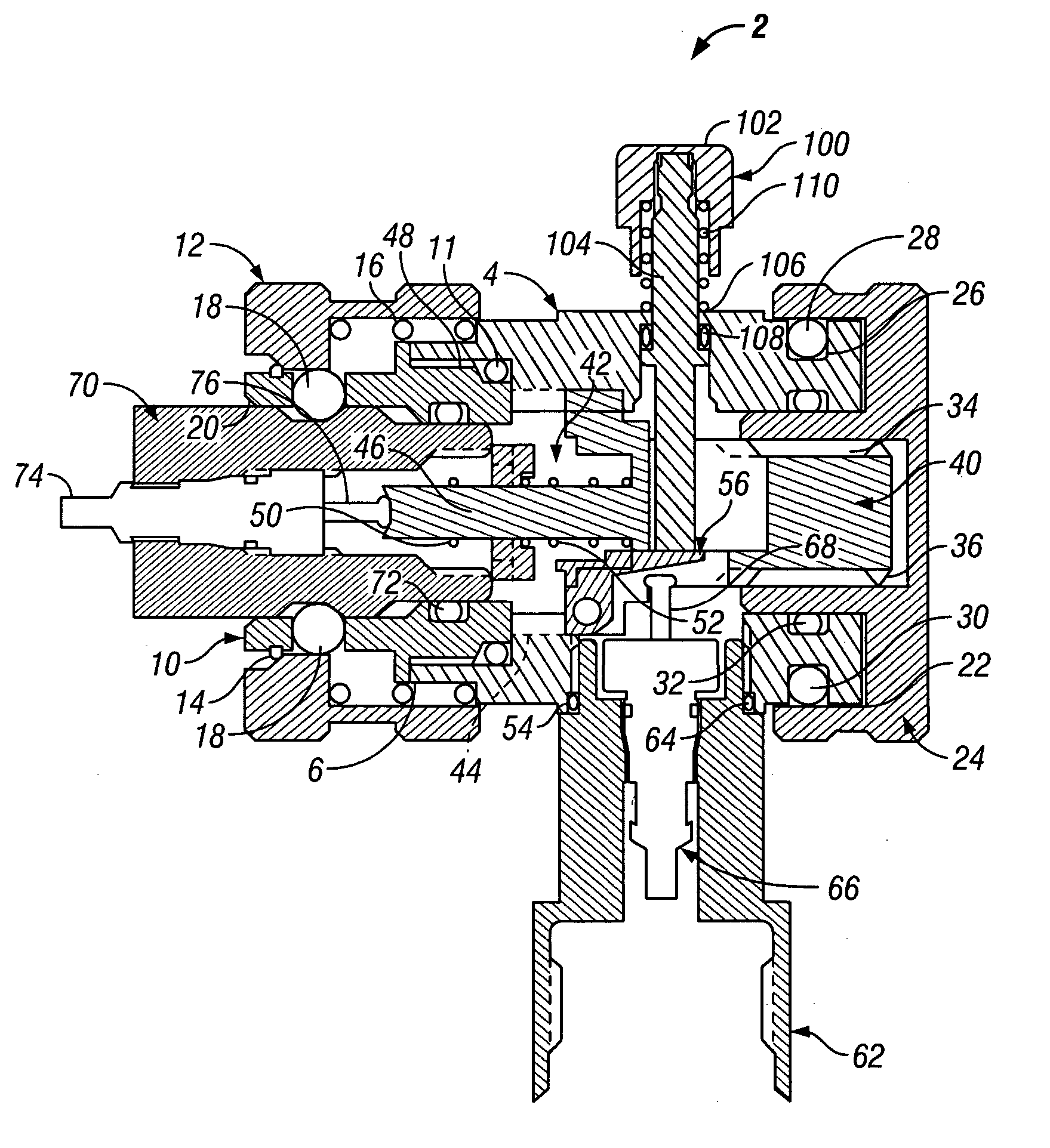
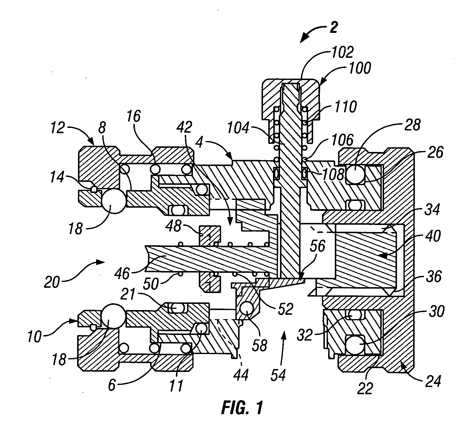
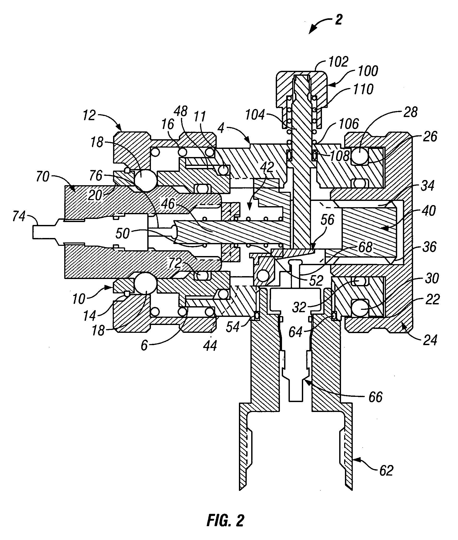
[0034] Referring to FIGS. 1-3, 5, and 6, coupling member 2 includes body 4. Body 4 has first end 6 attached to release sleeve assembly 8. Release sleeve assembly 8 includes adapter 10 which is attached by threads to first end 6. Alternatively, adapter 10 can be attached to first end 6 by pins, set screws, a snap ring, brazing, soldering, or swaging. O-ring 11 provides a fluid-tight seal between adapter 10 and body 4. Release sleeve 12 slides over adapter 10. Retaining ring 14 holds release sleeve 12 over adapter 10. Release sleeve spring 16 resides between release sleeve 12 and adapter 10 and pushes release sleeve 12 against retaining ring 14. When pushed against retaining ring 14, release sleeve 12 holds balls 18 within adapter 10. Balls 18 are distributed around the circumference of adapter 10. First end 6 includes orifice 20, which can receive a service port, which includes a valve, of a pressurized system. Balls 18 engage with the service port when the port is inserted into orif...


PUM


Abstract

A method and apparatus for servicing a pressurized system is described. A purge fitting can be used to vent the pressurized system. Venting can release a gas, such as air, from the system. The pressurized system can be a climate control system (e.g., an air conditioning or refrigeration system), a brake system, a hydraulic system, or a service device for servicing a climate control system. The purge fitting allows air that may be trapped in the pressurized system to be vented by depressing a purge actuator, such as a purge button attached to the fitting. The air can be vented from an opening adjacent to the actuator or other orifice. By purging air directly from the system, the amount of air introduced into the system during servicing can be minimized. The invention also features a coupling member that can be compact in size. The coupling member can include a self-sealing valve assembly that prevents opening the coupling member until a proper coupling interconnection with a system to be serviced has taken place. The purge fitting can be incorporated in the coupling member or other service device.

Description

CLAIM OF PRIORITY [0001] This application is a continuation of and claims priority to U.S. application Ser. No. 09 / 422,236 filed on Oct. 21, 1999, now U.S. Pat. No. 6,539,970, the entire contents of which is hereby incorporated by reference.BACKGROUND OF THE INVENTION [0002] The present invention relates to a method and apparatus for servicing a pressurized system, in particular an air conditioning or refrigeration system. [0003] Servicing couplings are commonly employed to facilitate charging and evacuation of a pressurized fluid system, such as a refrigeration system, an air conditioning system, or a hydraulic system. The service coupling connects to a service port of the system. The service coupling opens a service port of a system, allowing fluids, including liquids or gases, to be exchanged with the system. A quick-release interconnection between the service port and the service adapter can facilitate the servicing process. For example, when servicing a refrigeration or air con...

Claims


Application Information

Patent Timeline
Patent Type & Authority Applications(United States)
IPC IPC(8): B08B9/02F16L37/23F16L37/36F25B41/00F25B45/00
CPCB08B9/0321F16L37/23F25B2345/006F25B41/003F25B45/00F16L37/36Y10T137/4245Y10T137/87925Y10T137/0318Y10T137/87981Y10T137/0419Y10T137/88046Y10T137/87088Y10T137/87096
Inventor KNOWLES, STEVEN M.KALLEY, TERRENCE D.
Owner PRIME SOLUTIONS LLC
Why Eureka
Try Eureka