
Image-taking apparatus and system

a technology of image-taking apparatus and system, which is applied in the field of image-taking apparatus, can solve the problems of reducing the imaging light intensity of the camera body, requiring a long time to determine focus, and reducing the cost of the lens unit, so as to eliminate the disadvantage

Inactive Publication Date: 2009-01-13
CANON KK
View PDF5 Cites 0 Cited by
  • Summary
  • Abstract
  • Description
  • Claims
  • Application Information

AI Technical Summary

Benefits of technology

Ensures consistent focus detection and prevents defocus issues when switching viewfinder modes, providing a seamless user experience by maintaining focus accuracy and eliminating discomfort during mode transitions.

Problems solved by technology

In general, the contrast detection seeks a position having a maximum AF evaluation value by slightly moving the image-taking lens in the optical axis direction, and disadvantageously requiring a long time to determine focus.
Disadvantageously, the camera proposed in Japanese Patent Application, Publication No. 2000-162494 has the reduced imaging light intensity for the camera body due to the mirror that introduces the light into the focus detecting unit in the lens unit.
In addition, since each of the lens unit and the camera body has the focus detecting unit, the lens unit becomes large and expensive.

Method used


Image

  • Image-taking apparatus and system
  • Image-taking apparatus and system
  • Image-taking apparatus and system

Examples


Embodiment Construction

[0031]Referring now to the accompanying drawings, a description will be given of the preferred embodiment.

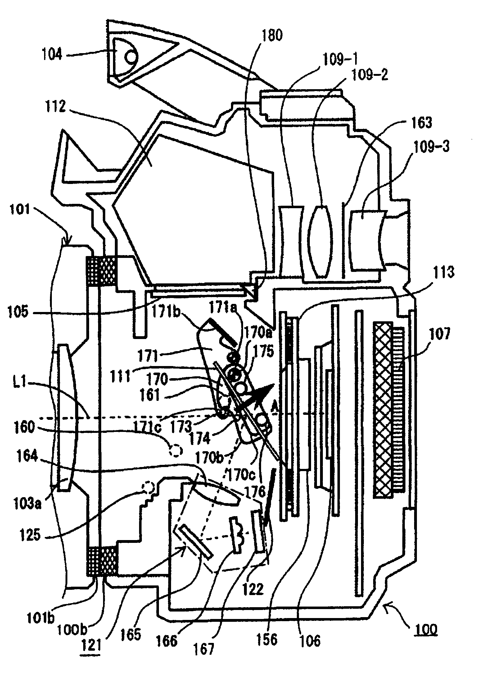
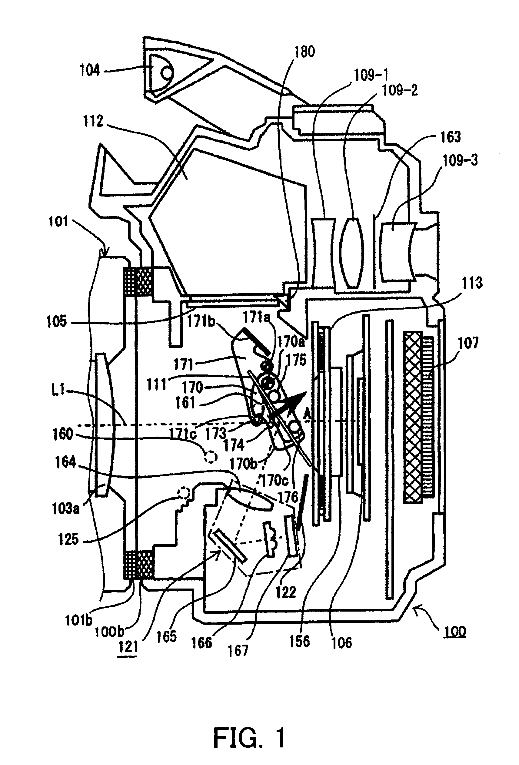
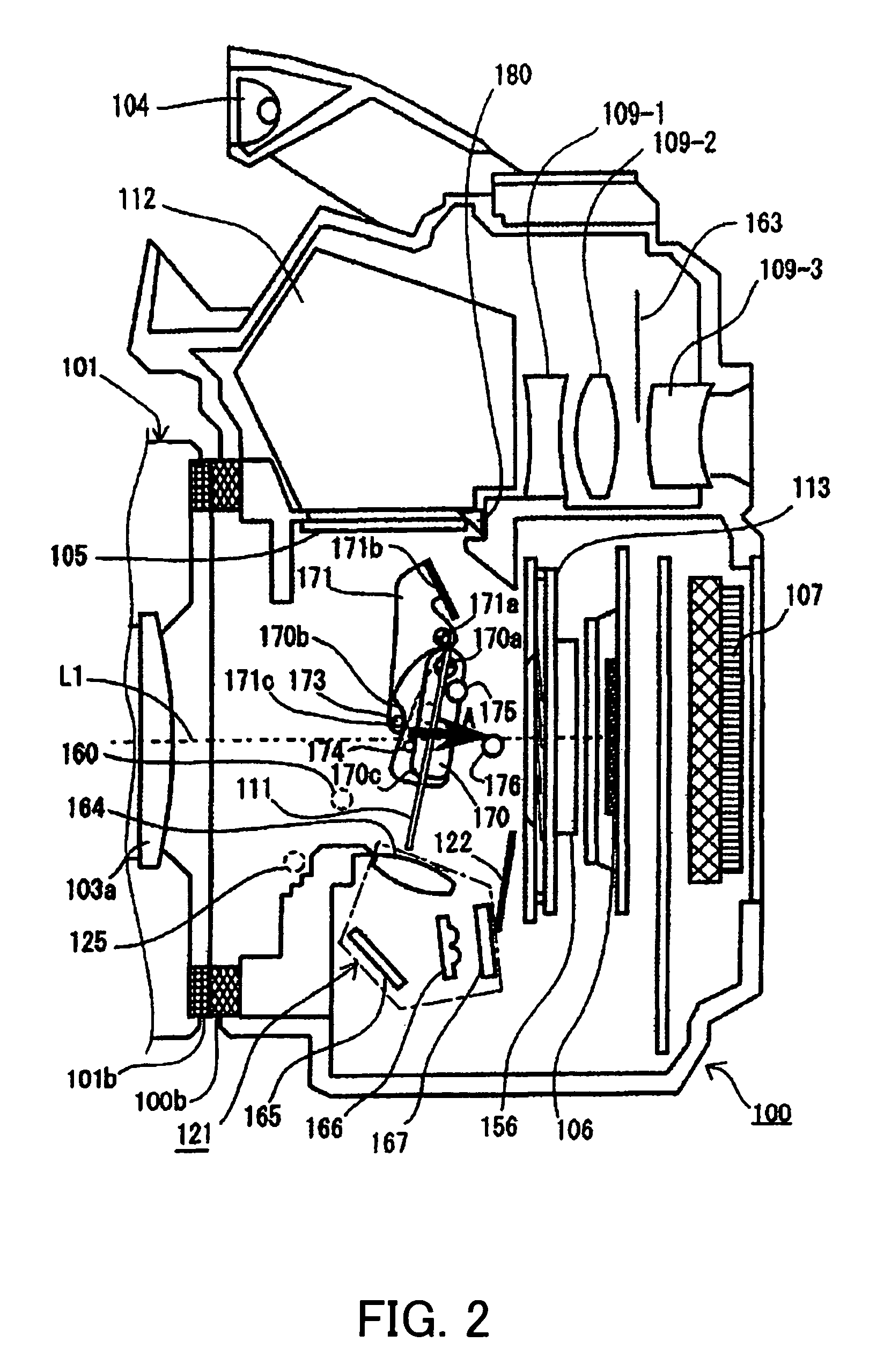
[0032]FIGS. 1 to 7 show a camera (or shooting) system according to one embodiment of the present invention. FIG. 6 shows a schematic optical structure of the camera system of this embodiment. This camera system includes a camera body (or an image-taking apparatus) and a lens unit that is detachably attached to the camera body.

[0033]The camera is a one-CCD digital color camera that uses an image-pickup device, such as a CCD and a CMOS sensor, drives the image-pickup device continuously or for each shot, and obtains an image signal indicative of a motion or still image. The image-pickup device is an area sensor that converts the exposure light into an electric signal for each pixel, and stores and reads electric charges corresponding to the received light intensity.

[0034]In FIG. 6, 100 denotes a camera body, and 101 denotes a lens unit that is detachable from the camera body 100. ...


PUM


Abstract

There is disclosed an image-taking apparatus that prevents a defocus of a subject image observed after a viewfinder mode switches when the focus control uses the same focus detecting unit for OVF and EVF modes. The image-taking apparatus includes a focus detecting unit for detecting focus of the image-taking lens, and a mirror unit for switching between a first state used to introduce the light from the image lens into the viewfinder optical system and the focus detecting unit, and a second state used to introduce the light to the image-pickup device and the focus detecting unit. The controller controls driving of the mirror unit and driving of a focus lens based on a detection result by the focus detecting unit. The controller prohibits the driving of the mirror unit while the focus lens is being driven.

Description

BACKGROUND OF THE INVENTION[0001]The present invention relates to an image-taking apparatus, and more particularly to an image-taking apparatus that enables a user to arbitrarily switch a viewfinder mode by operating a mirror unit.[0002]A single lens reflex camera as one image-taking apparatus reflects the light emitted from an image-taking lens via a mirror closer to an image surface than the image-taking lens, and introduces the light to the optical viewfinder (“OVF”). Thereby, a photographer can view an erect object image formed by the image-taking lens. The mirror is obliquely provided on a shooting optical path.[0003]In shooting an object image, the mirror retreats from the shooting optical path, and enables the light from the image-taking lens to such an imaging medium as a film and an image-pickup device, such as a CCD. After the shot, the mirror is obliquely arranged on the shooting optical path.[0004]Some digital single lens reflex cameras can select two types of focusing, ...

Claims


Application Information

Patent Timeline
Patent Type & Authority Patents(United States)
IPC IPC(8): H04N5/232H04N5/222G02B15/14G03B13/08G03B13/36G03B19/12H04N5/225
CPCG03B13/08G03B13/36G03B19/12H04N5/2254H04N5/23212H04N23/53H04N23/55
Inventor NOTO, GORO
Owner CANON KK
Learn More