Image correcting apparatus and method, program, storage medium, image reading apparatus, and image forming apparatus

a technology of image correction and image reading, which is applied in the field of image correction apparatus and method, program, storage medium, image reading apparatus, and image forming apparatus, can solve the problems of inability to achieve the shape from shading method, inconvenient method, and low recognition ra

Inactive Publication Date: 2009-01-13
RICOH KK
View PDF10 Cites 35 Cited by
  • Summary
  • Abstract
  • Description
  • Claims
  • Application Information

AI Technical Summary

Benefits of technology

[0133]The image forming apparatus can provide similar advantages to the aforementioned image correcting apparatus.

Problems solved by technology

The deteriorated image of the binding margin 101 is not readily readable and causes an extremely low recognition rate when characters on the image are recognized through an optical character reading (OCR) process.
However, the Shape from Shading method is not feasible because of a large amount of calculations and a long calculation time required for correcting distortions.
However, the method described in Reference 2 is not proper because it requires a special shape measuring device for measuring the shape of a book in accordance with the triangulation.
However, since conventional image correcting methods do not take into account the foregoing situation, they are not capable of sufficiently correcting the foregoing distortions in a scanned image, and moreover cause a lower image quality on the contrary.

Method used


Image

  • Image correcting apparatus and method, program, storage medium, image reading apparatus, and image forming apparatus
  • Image correcting apparatus and method, program, storage medium, image reading apparatus, and image forming apparatus
  • Image correcting apparatus and method, program, storage medium, image reading apparatus, and image forming apparatus

Examples


first embodiment

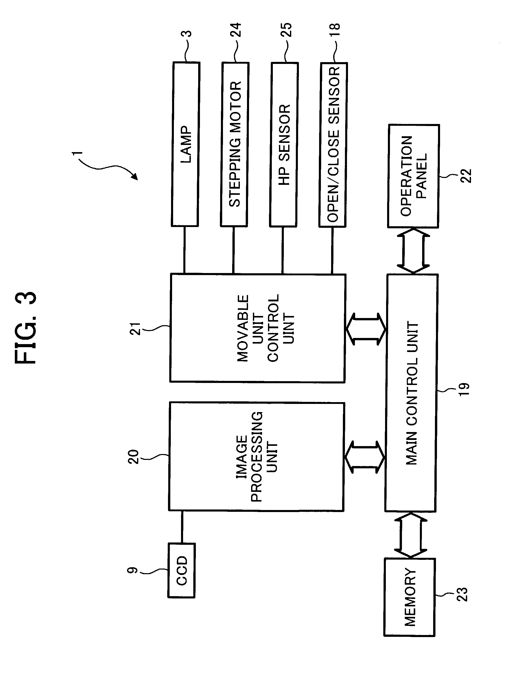
[0180]FIG. 4 is a block diagram illustrating the basic internal configuration of the image processing unit 20. As illustrated in FIG. 4, the image processing unit 20 comprises an analog video processor 26 for performing amplification, digital conversion and the like on an analog image signal read by the CCD 9 from a document; a shading correction processor 27 for performing a shading correction; an image data processor 28 for performing a variety of image data processing such as MTF correction, scaling, γ correction and the like on a digital image signal after the shading correction to generate a scanned image; and an image corrector 29 for implementing an image correcting function, which is a characteristic function of the first embodiment, on a scanned image. The digital image signal, after the foregoing image processing, is transmitted to the printer unit through the main control unit 19 and served for forming an image.

[0181]As illustrated in FIG. 5, the main control unit 19 comp...

second embodiment

[0242]It can be seen that the three-dimensional shape is found from a two-dimensional distortion amount by the equation (12). In this event, while the distortion amount (y′−y) and distance y can be measured in the image, the second embodiment calculates them from the distance between a straight section and a curvilinear section of a character string or a rule. The focal distance F of the lens is a known amount determined by the scanner unit 1, and represented by a set value of the scanner unit 1 or a calibration value of the lens.

[0243]Subsequently, the CPU 31 corrects the scanned image for the distortion based on the three-dimensional shape (step S64), corrects the scanned image for the luminance (step S65), and corrects the image for blurred characters thereon (step S66).

[0244]Since the correction of the image for the distortion at step S64 is identical to that performed at steps S25-S27 described in the first embodiment, description thereon is omitted.

[0245]Likewise, since the co...


PUM


Abstract

An image correcting apparatus is provided for preventing a degraded image quality which can be caused by a three-dimensional distortion correction made to a scanned image distorted in a trapezoidal shape. Divergent distortion angles α, β of a scanned image are detected using a page contour of a book document which can be found near the upper or lower edge of the scanned image in a main scanning direction. The scanned image is corrected for a divergent distortion based on the divergent distortion angles α, β, followed by a correction of the scanned image for a shape distortion in a sub-scanning direction. In this way, the image quality can be prevented from degradation possibly caused by the three-dimensional distortion correction, if made to such a scanned image distorted in a trapezoidal shape.

Description

BACKGROUND OF THE INVENTION[0001]1. Field of the Invention[0002]The present invention relates to an image correcting apparatus and method which can correct a scanned image distorted in a trapezoidal shape for a three-dimensional distortion correction made without causing a degraded image quality, a program for implementing the image correcting apparatus in a computer, a storage medium which has the program stored thereon, and an image reading apparatus and an image forming apparatus which incorporate the image correcting apparatus.[0003]2. Description of the Related Art[0004]A flat bed scanner typically reads flat sheet documents. Specifically, the flat bed scanner comprises a contact glass and a pivotable pressure plate disposed over the contact glass. After a document sheet is carried on the contact glass, the pressure plate is closed for scanning the document sheet. However, documents intended for scanning are not limited to such flat sheet ones, but certain pages in a book docum...

Claims


Application Information

Patent Timeline
Patent Type & Authority Patents(United States)
IPC IPC(8): H04N1/04G06T1/00G06K9/32G06T5/00H04N1/10H04N1/107H04N1/387H04N1/40
CPCG06K9/3283G06T5/006H04N1/387G06T5/003G06T5/007G06T2207/10008G06T2207/30176G06V30/1478
Inventor GUAN, HAIKEARAKI, TADASHI
Owner RICOH KK
Why Eureka
Try Eureka