Adaptive artificial vision method and system

Inactive Publication Date: 2009-01-13
SONY FRANCE
View PDF6 Cites 9 Cited by
  • Summary
  • Abstract
  • Description
  • Claims
  • Application Information

AI Technical Summary

Benefits of technology

[0011]The present invention aims at overcoming the above-mentioned drawbacks and at enabling efficient bootstrapping of

Problems solved by technology

Unfortunately in some situations, neither of these two conditions can be met.
In such cases, segmenting and recognizing objects become a bootstrapping problem that can be summarized in the following way:Segmentation alg

Method used


Image

  • Adaptive artificial vision method and system
  • Adaptive artificial vision method and system
  • Adaptive artificial vision method and system

Examples


Embodiment Construction

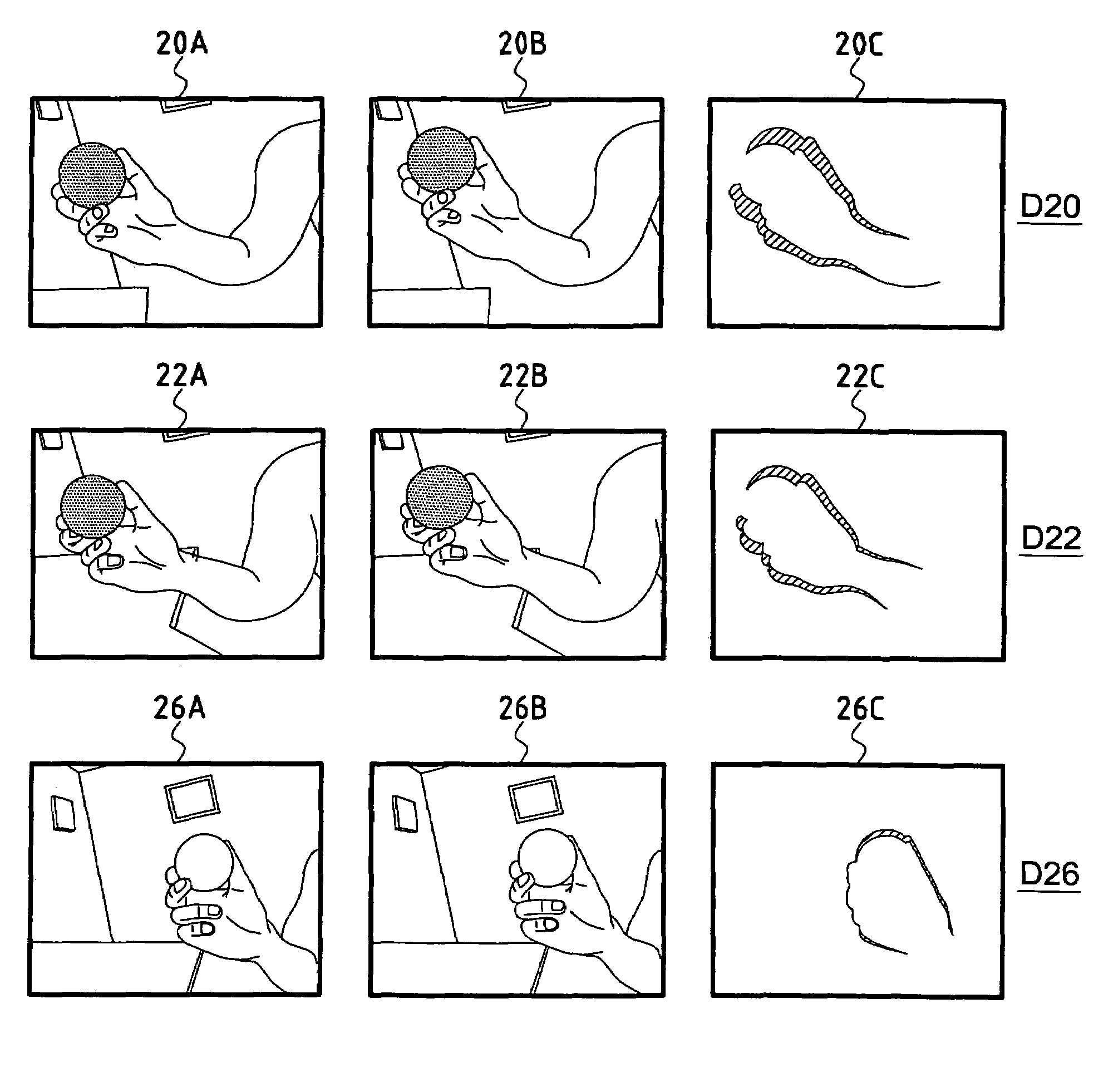
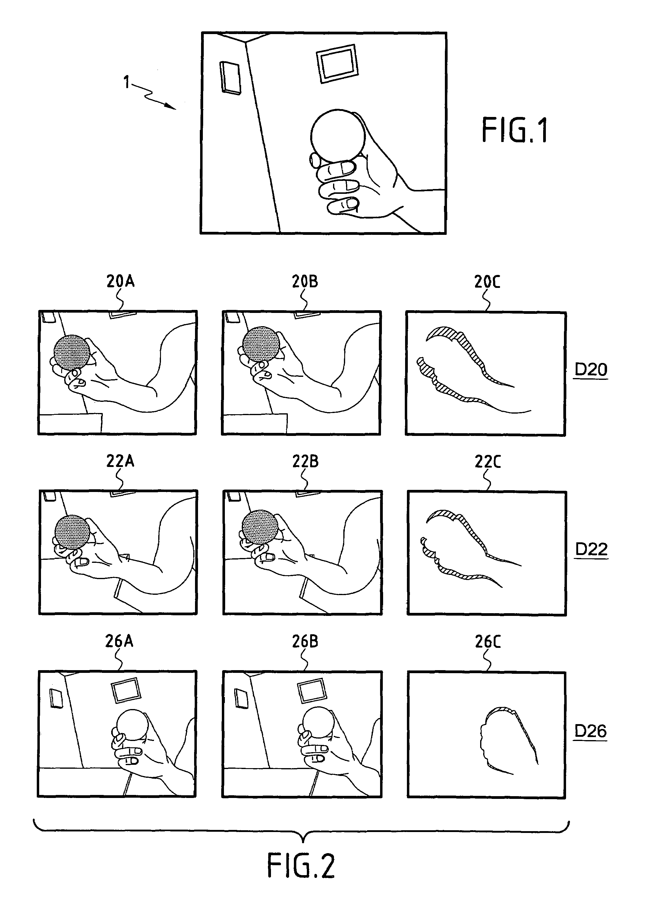
[0049]The adaptive artificial vision system according to the invention is conceived in such a manner that it is capable of bootstrapping object and event recognition.

[0050]The method and system according to the invention start with very crude recognition capabilities. The system may be called impressionist since it is adapted to perceive patches which are elementary visual parts for describing dynamic or static events. A dynamic event is usually defined by a movement whereas a static event is defined by an object.

[0051]The patches are constructed by the system to describe its visual perception at the lowest level. As the system accumulates visual experiences, it attempts to integrate patches together in order to discover stable sets. This integration happens both in the time and the spatial domain. After a while, the system becomes capable of recognizing reoccuring movements. After reaching this stage, it tries to extract the structure of objects involved in the movements it detects...


PUM


Abstract

The adaptive artificial vision method comprises the following steps: (a) defining successive couples of timesteps (t−1, t; t, t+1; . . . ) synchronized by a clock (101), (b) comparing two successive images (It−, It; It, It+1, . . . ) from an input device (102, 103) at each couple of synchronized timesteps (t−1, t; t, t+1; . . . ) spaced by a predetermined time delay τ0 for obtaining a delta image Δt which is the result of the computation of the distance between each pixel of the two successive images (It−1, It; It, It+1, . . . ) in view of characterizing movements of objects, (c) extracting features from the delta image Δt for obtaining a potential dynamic patch Pt which is compared with dynamic patches previously recorded in a repertory which is progressively constructed in real time from an initial void repertory, (d) selecting the closest dynamic patch Di in the repertory or if no sufficiently close dynamic patch still exists, adding the potential dynamic patch Pt to the repertory and therefore obtaining and storing a dynamic patch Di from the comparison of two successive images (It−1, It; It, It+1, . . . ) at each couple of synchronized timesteps (t−1, t; t, t+1; . . . ), and (e) temporally integrating stored dynamic patches Di of the repertory in order to detect and store stable sets of active dynamic patches representing a characterization of a reoccuring movement or event which is observed. A process of static pattern recognition may then be efficiently used.

Description

BACKGROUND OF THE INVENTION[0001]1. Field of the Invention[0002]The present invention relates to an adaptive artificial vision method and to an adaptive artificial vision system.[0003]2. Technical Background[0004]In most artificial vision systems, objects are either pregiven or they do not exist.[0005]Some systems perform image segmentation based on the particular characteristics of an image (color, boundaries, etc.). These systems have no notion of objects. They just extract regions which seem interesting in themselves. They work well if the background on which the “objects” are presented is known or strongly constrained (e.g. colored objects on a white floor). In such cases the segments automatically extracted can be considered as the “contour” of some objects.[0006]Other systems perform object identification given a set of predefined objects that they use as models. If the models are of sufficiently good quality, performances of such systems can be very good. See for example the ...

Claims


Application Information

Patent Timeline
IPC IPC(8): G06K9/00G06K9/64G06T7/00G06K9/68G06T7/20
CPCG06T7/2006G06T7/215
Inventor KAPLAN, FREDERICK
Owner SONY FRANCE
Why Eureka
Try Eureka