Fuel-filtering device

a technology of fuel filtering and filtering chamber, which is applied in the direction of filtration separation, machine/engine, separation process, etc., can solve the problems of reducing the amount of foreign materials sent in the fuel pump and prolonging the life of the fuel pump

Inactive Publication Date: 2009-01-20
NIFCO INC
View PDF16 Cites 24 Cited by
  • Summary
  • Abstract
  • Description
  • Claims
  • Application Information

AI Technical Summary

Benefits of technology

[0013]According to the structure of the filtering device of the first aspect of the invention, since the first filter layer is formed of the woven mesh having a fine mesh for improved water separation, water is separated more effectively in the inner space of the filter body as compared with an extruded mesh made of a synthetic resin.
[0014]Also, foreign materials in the fuel, which have passed through the first filter layer, can be effectively removed by the second filter layer, which is formed of the non-woven fabric and disposed just inside the first filter layer. Accordingly, since the number of foreign materials sent in the fuel pump is decreased, the fuel pump has a prolonged life.
[0019]Also, since the intermediate layer formed of the non-woven fabric is sandwiched between the outer layer and the inner layer formed of the mesh, the shape of the non-woven fabric constituting the intermediate layer can be maintained by the outer layer and the inner layer, so that the filter body is maintained in an adequately inflated bag form.
[0021]According to the structure of the filtering device of the fourth aspect of the invention, by connecting one end portion of the cylindrical socket body to the fuel suction port, the filtering device can be adequately attached to the fuel suction port.
[0023]According to the structure of the fuel-filtering device of the fifth aspect of the invention, the outer layer constituting the filter body is prevented from directly contacting the inner wall surface of the lower section of the fuel tank. Therefore, the outer layer will not be worn out with time since the inner wall surface of the lower section of the fuel tank does not slide against the outer layer when the inner wall surface of the lower section of the fuel tank moves (that is, when the fuel tank T is expanded or shrunk) due to the change in the internal pressure of the fuel tank.

Problems solved by technology

Accordingly, since the number of foreign materials sent in the fuel pump is decreased, the fuel pump has a prolonged life.

Method used


Image

  • Fuel-filtering device
  • Fuel-filtering device
  • Fuel-filtering device

Examples


first embodiment

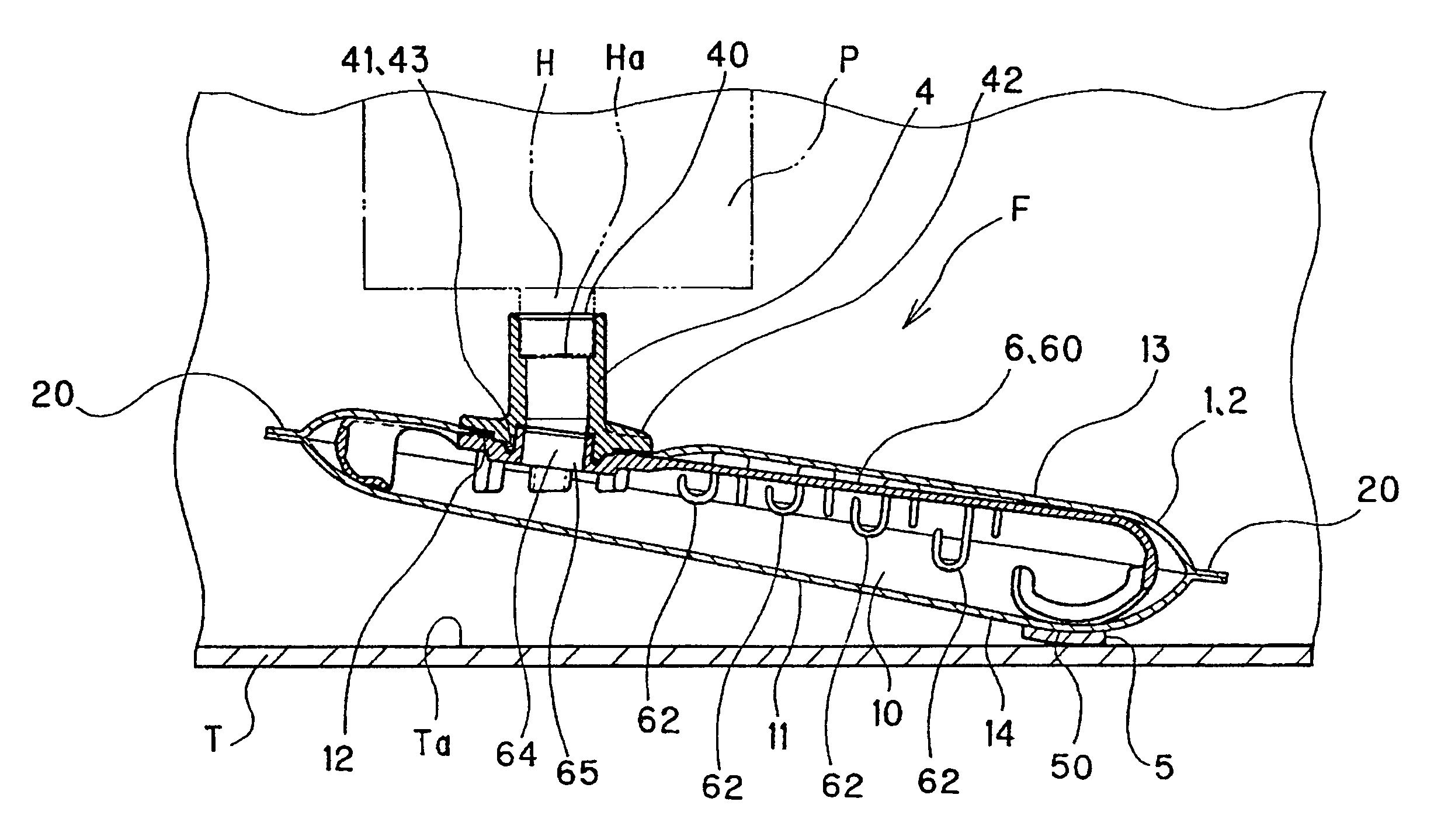
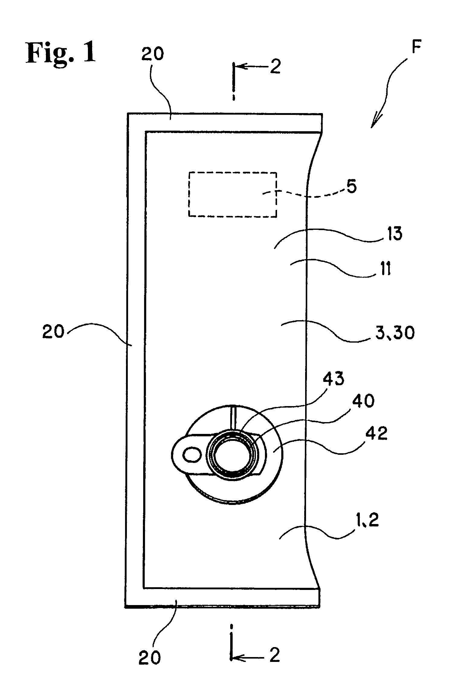
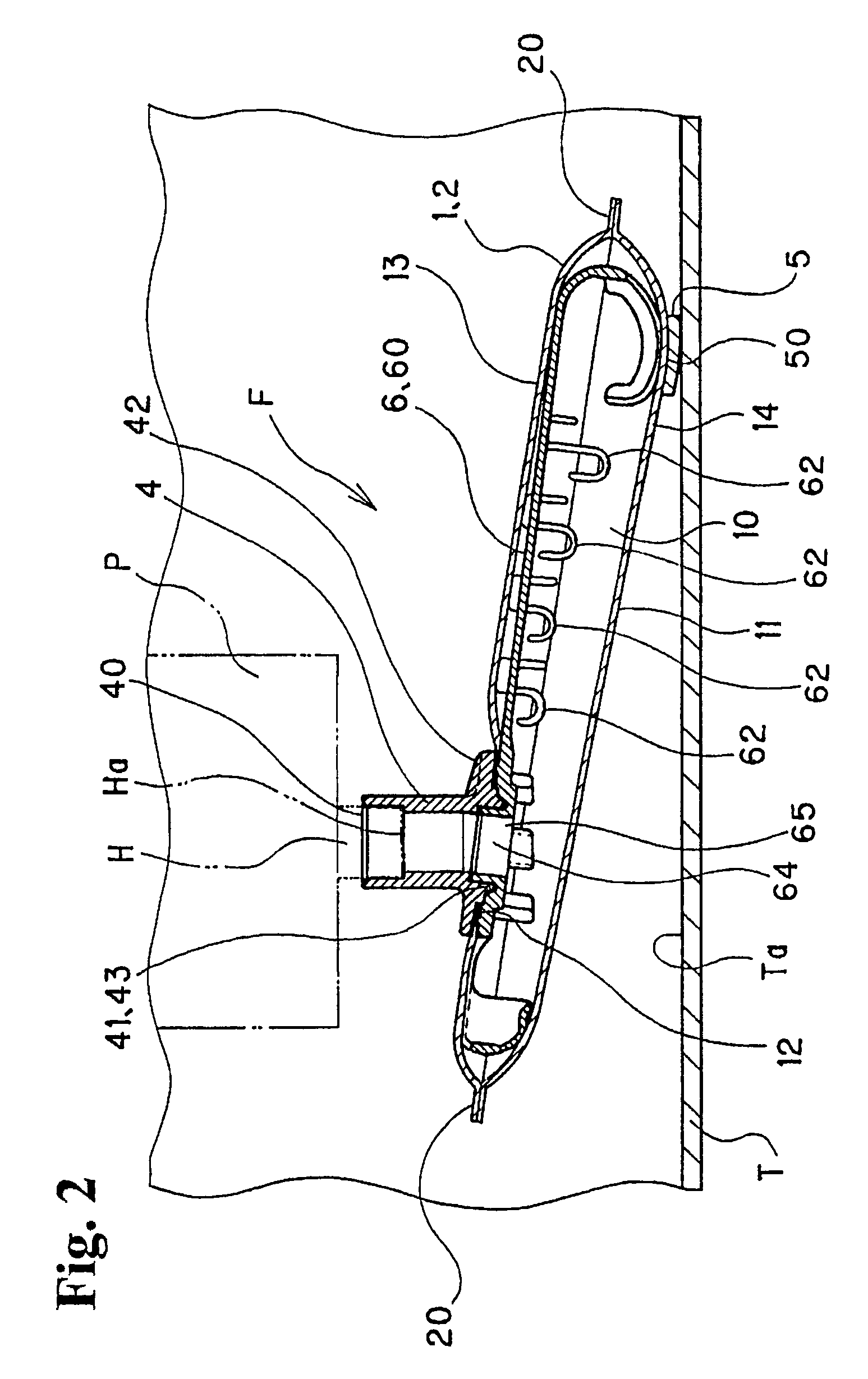
[0054]More specifically, FIG. 1 shows the filtering device F according to the invention seen from above, and FIG. 2 shows a state that the filtering device F is in use, in which the filtering device F is shown in a sectional view. Also, FIG. 3 shows the filtering device F seen from a right side in FIG. 2. FIG. 4A shows an enlarged sectional view of a filter body 1 of the filtering device F, and FIG. 4B shows an enlarged sectional structure of another example of the filter body of the filtering device F. Also, FIG. 5 to FIG. 7 show a cylindrical socket body 4 forming the filtering device F, and FIG. 8 to FIG. 10 show a spacing member 6. Further, FIG. 11 shows a filter base material 2, which is shown in a developed view to explain an insert-molding method where the developed base material 2 is placed in a metallic mold to mold the cylindrical socket body 4 and a contact section 5. In FIG. 11, the cylindrical socket member 4 and the contact section 5 are placed in a mold at positions s...

second embodiment

[0055]FIG. 12 shows the filtering device F′ according to the invention seen from above, and FIG. 13 is a sectional view of the filtering device F′ in a state that the filtering device F′ is in use. FIG. 14 shows the filtering device F′ seen from a right side in FIG. 13. Further, FIG. 15 shows an enlarged sectional structure of a filter body 1 of the filtering device F′.

[0056]First, the first embodiment shown in FIG. 1 to FIG. 11 will be explained. The filtering device F according to the first embodiment of the invention is attached to a fuel suction port Ha disposed inside a fuel tank T, to thereby remove water and foreign materials in fuel transferred to an internal combustion engine through the fuel suction port Ha.

[0057]Typically, the filtering device F is attached to the fuel suction port Ha of a suction pipe H inside the fuel tank T. The fuel is transferred to the internal combustion engine side through the fuel suction port Ha by a fuel pump P disposed inside the fuel tank T, ...


PUM

PropertyMeasurementUnit
diameteraaaaaaaaaa
diameteraaaaaaaaaa
diameteraaaaaaaaaa

Abstract

A fuel-filtering device is disposed inside a fuel tank for filtering a fuel. The fuel-filtering device includes a filter body having a bag shape and a communication hole, and is formed of a plurality of laminated filter layers. The laminated filter layers includes an outside filter layer formed of a woven mesh, an inside filter layer formed of a non-woven fabric, and at least one intermediate filter layer disposed between the outside filter layer and the inside filter layer and formed of a non-woven fabric. The filter body is formed of at least one of a polyethylene fiber and a polypropylene fiber and has mesh sizes decreasing from the outside filter layer toward the inside filter layer.

Description

CROSS REFERENCE TO RELATED APPLICATION[0001]This is a continuation-in-part application of patent application Ser. No. 10 / 190,601 filed on Jul. 9, 2002.BACKGROUND OF THE INVENTION AND RELATED ART STATEMENT[0002]The present invention relates to a fuel-filtering device attached to a fuel suction port located in a fuel tank.[0003]A fuel pump transfers fuel in a fuel tank to an internal combustion engine via a suction pipe provided inside the fuel tank. In order to remove water from the transferred fuel as well as to prevent foreign materials from being sent to the fuel pump, a filter is attached to a fuel suction port of the suction pipe.[0004]This type of filter has been disclosed in Japanese Patent Publication (KOKAI) No. 2000-246026. The filter is formed in a bag shape, and has an outer layer made of an extruded mesh and an inner layer made of a non-woven fabric. Also, a spacing member is provided inside the filter for maintaining an inflated bag shape of the filter.[0005]According t...

Claims


Application Information

Patent Timeline
Patent Type & Authority Patents(United States)
IPC IPC(8): B01D29/46B01D29/13B01D35/027F02M37/22
CPCB01D35/0273F02M2037/228F02M37/50
Inventor SATO, HIROJIKURIHARA, KAZUMASAKOBAYASHI, YASUTOMOKIMISAWA, TOSHIHIDEKOJIMA, TAKESHI
Owner NIFCO INC
Why Eureka
Try Eureka