Head mounted apparatus

a head and apparatus technology, applied in the direction of instruments, static indicating devices, optical elements, etc., can solve the problems of unstable attachment, different left and right adjustment amounts, user discomfort, etc., and achieve the effect of simple structure and good mounting and manipulating capabilities

Inactive Publication Date: 2009-01-20
CANON KK
View PDF11 Cites 9 Cited by
  • Summary
  • Abstract
  • Description
  • Claims
  • Application Information

AI Technical Summary

Benefits of technology

[0008]The present invention is directed to a head mounted apparatus having a mount mechanism with a simple structure and good mounting and manipulating capabilities.

Problems solved by technology

However, the mount mechanism disclosed in U.S. Pat. No. 3,576,985 is a type that adjusts the left and right adjusting mechanisms independently, causing different left and right adjusting amounts.
In particular, an elastic band that holds the occipital-region compressing portion provides the left and right adjusting amounts with a large degree of freedom, causing the occipital-region compressing portion to laterally shift relative to the frontal-region compressing portion, and making the attachment unstable.
In addition, in that case, a laterally asymmetrical force applied to the occipital region causes a user to feel uncomfortable.
The adjusting mechanism using a ratchet mechanism problematically generates noises during adjustment, and its stepwise adjustments cannot provide sufficiently fine mount capability.
On the other hand, the mount mechanism disclosed in Japanese Patent No. 3,042,353 requires one hand to support the head mounted apparatus and the other hand to manipulate the adjusting mechanism, posing bad manipulating or mounting problems.

Method used


Image

  • Head mounted apparatus
  • Head mounted apparatus
  • Head mounted apparatus

Examples


first embodiment

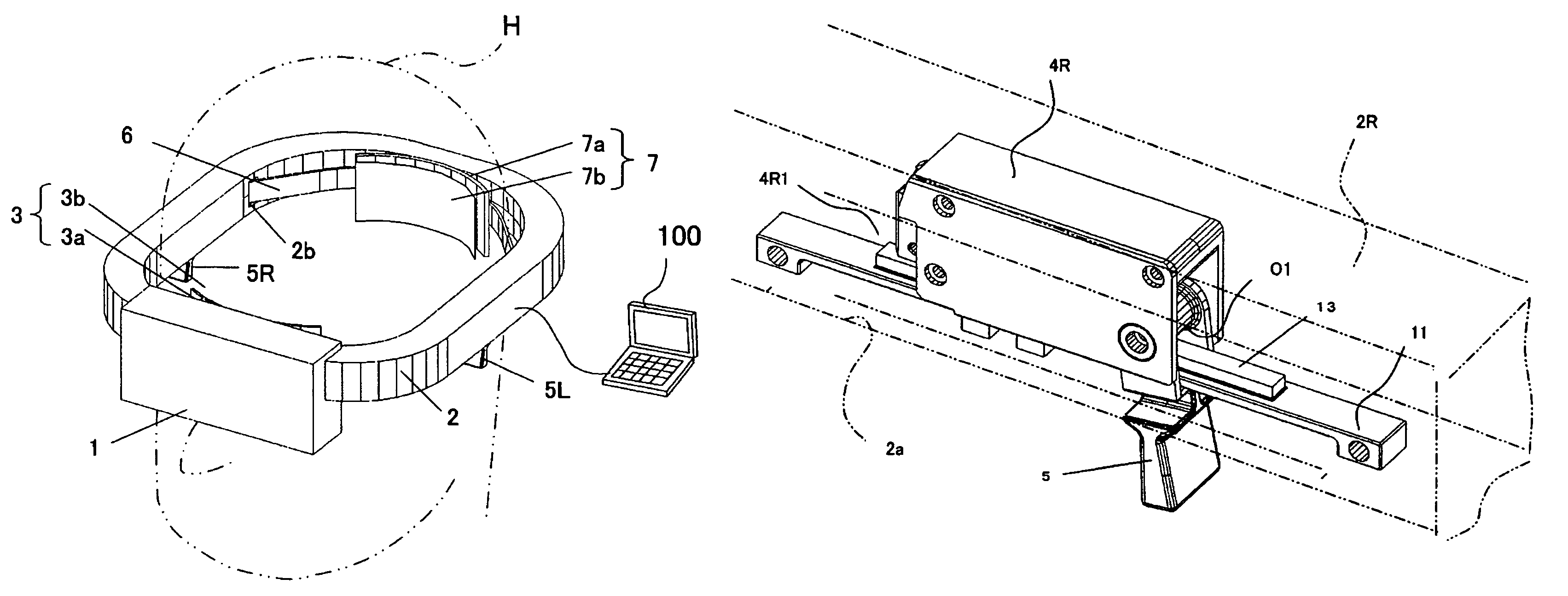
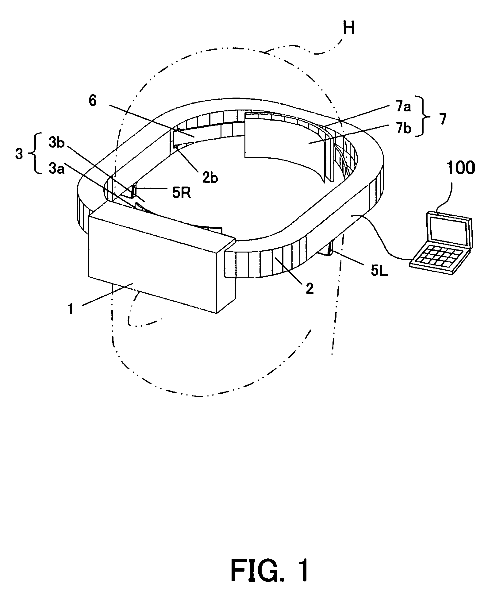
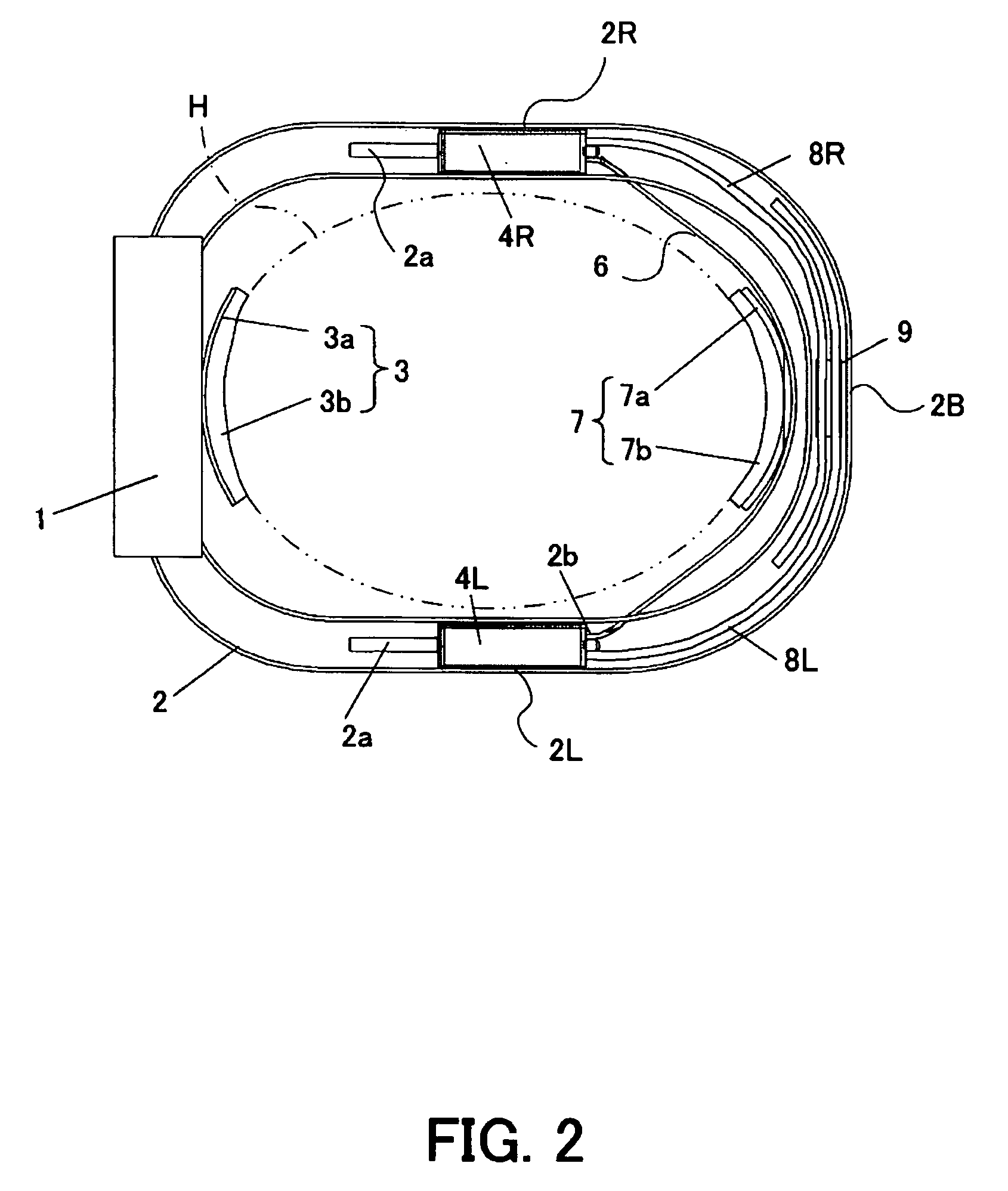
[0022]FIG. 1 shows a head mounted display as a head mounted apparatus according to a first embodiment of the present invention. FIG. 2 shows an internal structure of a frame in the mount mechanism in the head mounted display.

[0023]The head mounted display body or apparatus body 1 is arranged in front of a viewer's head H or eyes. Responsive to an image signal from an image supply apparatus 100, such as a personal computer (“PC”) and a DVD player, the head mounted display body 1 includes, as shown in FIG. 1, an image on an inside display device, such as a liquid crystal panel. An inside optical system magnifies and displays the image on the display device.

[0024]In the following description, the front, back, left, right, top and bottom correspond to those of the head H mounted with the head mounted display. The longitudinal direction can be a direction from the front to the back, and the lateral direction can be a direction from the left to the right.

[0025]2 denotes a rigid frame that...

second embodiment

[0050]FIG. 7 shows a head mounted display as a head mounted apparatus according to a second embodiment of the present invention. FIG. 8 shows an internal structure of a frame in the mount mechanism in the head mounted display. This embodiment designates the same reference numerals the elements similar to those in the first embodiment, and omits a description.

[0051]21 denotes a U-shaped frame shape when viewed from a top. The head mounted display body 1 is fixed onto a front portion of the frame 21. The front compressing portion 3 similar to that in the first embodiment is attached to an approximately center in the lateral direction on a plane opposite to the head mounted display 1 at the front portion of the frame 21. The frame 21 has a rectangular frame section in the longitudinal direction, similar to the first embodiment.

[0052]The left and right adjuster 4L and 4R are housed in longitudinally extending portions at the left and right sides of the frame 21 or in the left and right ...


PUM


Abstract

A head mounted apparatus mounted on a head of a user includes an apparatus body to be mounted on a front side of the head, a frame for supporting the apparatus body, the frame extending in a longitudinal direction at both sides of the head when the frame is mounted on the head, a front compressing portion provided on the frame or the apparatus body, and compressed against a frontal region of the head, first and second adjusters provided at both sides of the frame so that the first and second adjusters can move in the longitudinal direction relative to the frame, a back member that includes a back compressing portion compressed against an occipital region of the head, and is held by the first and second adjusters, and an interlock mechanism for enabling, as one of the first and second adjusters moves relative to the frame, the other of the first and second adjusters to move with the same moving amount relative to the frame in the same direction as the one.

Description

BACKGROUND OF THE INVENTION[0001]The present invention relates to a head mounted type equipment or head mounted apparatus, such as a head mounted display, and more particularly to a head mounted apparatus that includes an attachment or mount mechanism to be mounted on a user's head.[0002]A head mounted display is widely used because of easy image viewing on a wide screen, easy formations of stereoscopic visions, and mobility with a user. A mount mechanism holds the head mounted display on the front head side and includes a portion compressed against the frontal region, and a portion compressed against the occipital region. The mount mechanism fits the head by moving forward the occipital-region compressing portion after these portions are positioned at the front and back of the head. An adjusting mechanism that adjusts an interval between the frontal-region and occipital-region compressing portions to the head size can be provided on the left and right sides or on the backside of th...

Claims


Application Information

Patent Timeline
Patent Type & Authority Patents(United States)
IPC IPC(8): G06F1/16
CPCG02B27/0176
Inventor NAKABAYASHI, TAKAAKISAITO, YOSHIHIROOKUMA, TOSHIYUKIISHINO, TOSHIKI
Owner CANON KK
Why Eureka
Try Eureka