
Applying distributed simulation techniques to hardware emulation

a hardware emulation and distributed simulation technology, applied in the field of computer systems, can solve the problems of emulation servers, simulators may not be able to simulate the entire model, and single-system simulation has become less desirabl

Active Publication Date: 2009-01-20
ORACLE INT CORP
View PDF47 Cites 46 Cited by
  • Summary
  • Abstract
  • Description
  • Claims
  • Application Information

AI Technical Summary

Benefits of technology

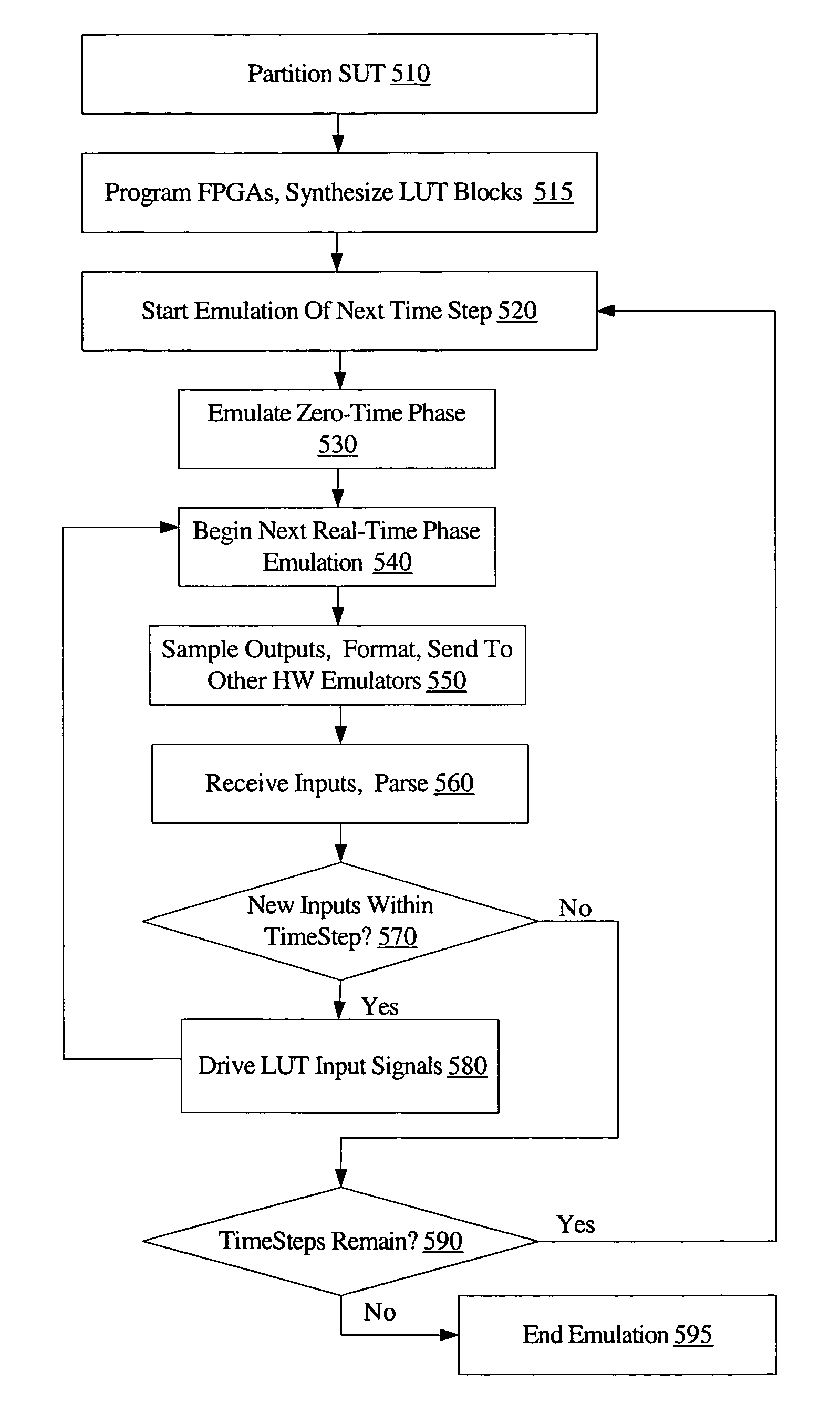
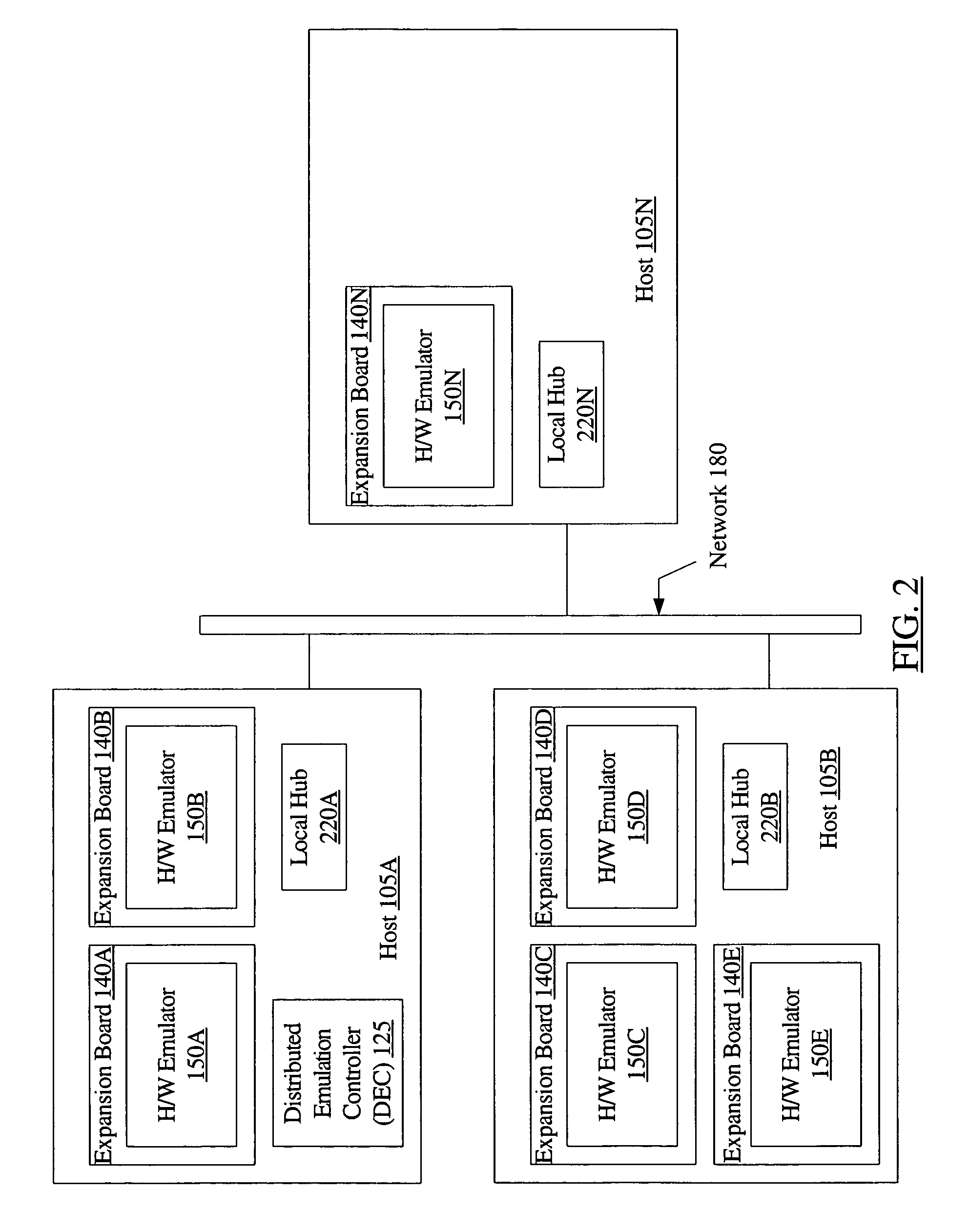
[0008]Various embodiments of systems and methods for applying distributed software simulation techniques to hardware emulation are disclosed. According to a first embodiment, the system may include a first hardware emulator mounted on a first expansion board at a first host, and a second hardware emulator mounted on a second expansion board at a second host. The first hardware emulator may be configured to emulate a first portion of a system under test, and the second hardware emulator may be configured to emulate a second portion of the system under test, and the first and second hardware emulators may coordinate an emulation of the system under test using one or more messages, i.e., a coordination of an emulation of the system under test may be accomplished using communications between the first and second hardware emulators. By using expansion boards for the hardware emulators, and allowing multiple emulators spread over multiple hosts to coordinate distributed emulation, a flexible and inexpensive mechanism for hardware emulation of large or complex electronic systems may be implemented.

Problems solved by technology

However, as the electronic systems (and the components forming systems) have grown larger and more complex, single-system simulation has become less desirable.
In some cases, the simulators may not be capable of simulating the entire model.
Hardware emulation has typically been performed using expensive, often proprietary emulation servers that may contain custom-built hardware emulation devices.
Such emulation servers may, for example, be limited to using a maximum number of emulation devices such as field programmable gate arrays (FPGAs) that may be incorporated within the proprietary design of the emulation server.
For large and complex designs, however, the total amount of design verification required may exceed the emulation capacity supported by an emulation server.

Method used


Image

  • Applying distributed simulation techniques to hardware emulation
  • Applying distributed simulation techniques to hardware emulation
  • Applying distributed simulation techniques to hardware emulation

Examples


Embodiment Construction

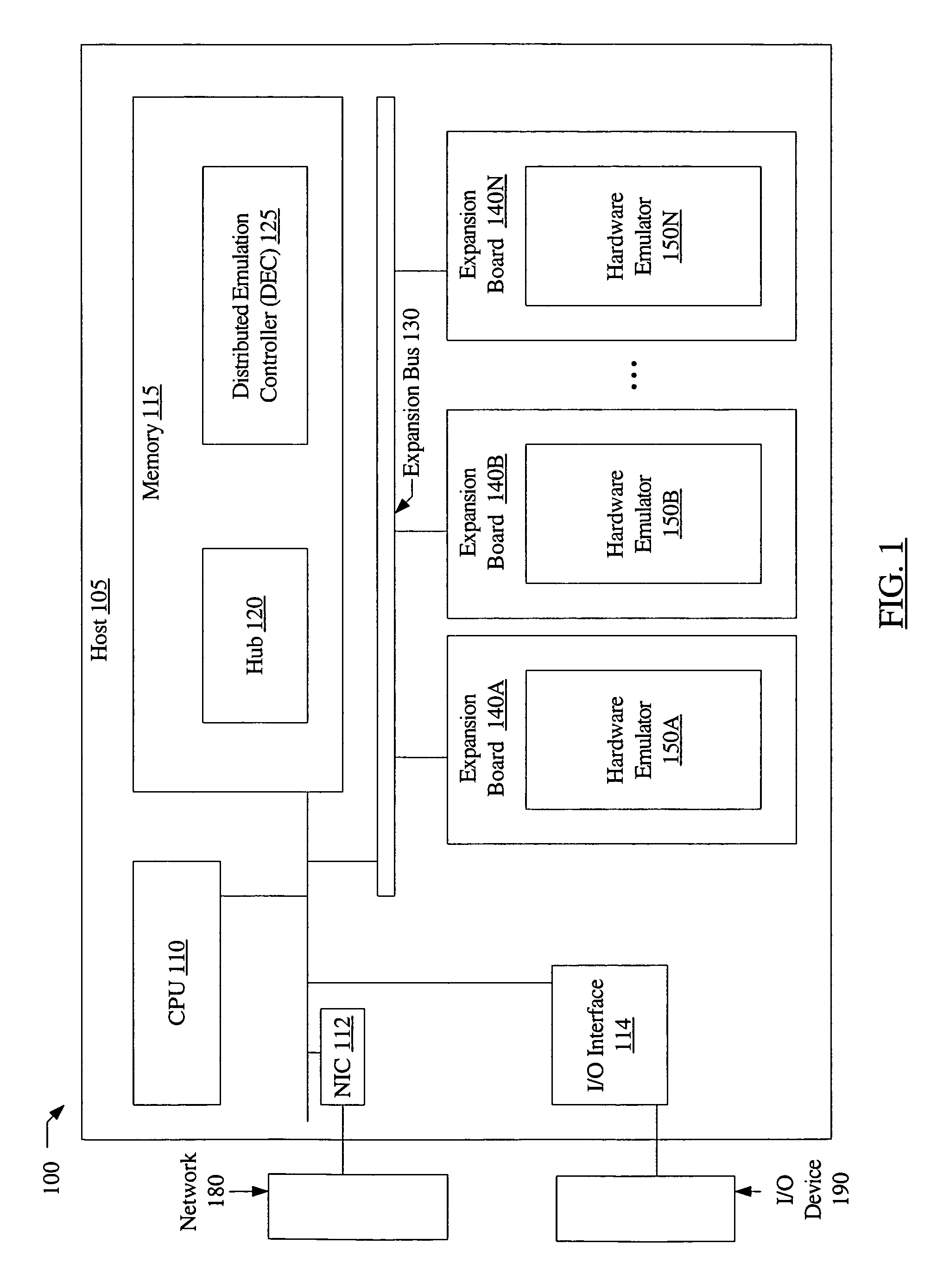
[0019]FIG. 1 is a block diagram of one embodiment of a distributed design verification system 100. In the embodiment of FIG. 1, the distributed design verification system (DDVS) 100 includes host 105, comprising a central processing unit (CPU) 110, memory 115, an expansion bus 130 and a plurality of expansion boards 140A-140N (which may be referred to herein as expansion boards 140) linked to the expansion bus 130. As used herein, an expansion board is defined as a printed circuit board that may be inserted into a computer host (e.g., using expansion slots) to provide or enhance a specific capability. Each expansion board 140 may include a respective hardware emulator 150—e.g., hardware emulator 150A may be mounted on expansion board 140A, hardware emulator 150B may be mounted on expansion board 140B, etc. In the depicted embodiment, memory 115 may include a hub 120 and a distributed emulation controller (DEC) 125. That is, hub 120 and DEC 125 may each comprise software instructions...


PUM


Abstract

A system for applying distributed software simulation techniques to hardware emulation may include a first hardware emulator mounted on a first expansion board at a first host, and a second hardware emulator mounted on a second expansion board at a second host. The first hardware emulator may be configured to emulate a first portion of a system under test, and the second hardware emulator may be configured to emulate a second portion of the system under test, and the first and second hardware emulators may coordinate an emulation of the system under test using one or more messages, i.e., a coordination of an emulation of the system under test may be accomplished using communications between the first and second hardware emulators.

Description

BACKGROUND OF THE INVENTION[0001]1. Field of the Invention[0002]This invention relates to the field of computer systems and, more particularly, to distributed hardware emulation environments.[0003]2. Description of the Related Art[0004]Generally, the development of components for an electronic system such as a computer system includes design verification of the components, which may be accomplished, for example, by simulation of models of the components, or by hardware emulation of the components. During design verification, the specified functions of each component may be tested and, when incorrect operation (a bug) is detected, the model or emulation circuitry of the component may be changed to generate correct operation. Once design verification is complete, the component may be fabricated. Since many of the bugs may have been detected in design verification, the component may be more likely to operate as specified and the number of revisions to hardware may be reduced. Simulatio...

Claims


Application Information

Patent Timeline
IPC IPC(8): G06F9/455G06F17/50G06F9/44
CPCG06F17/5027G06F30/331
Inventor CAVANAGH, CARLSIVIER, STEVEN A.
Owner ORACLE INT CORP
Learn More