Combination hydrophobic/hydrophilic filters/reservoirs for controlling fluid flow

a technology of hydrophobic and hydrophilic filters, applied in the direction of carpet cleaners, erasing devices, applications, etc., can solve the problems of inability to meet the needs of fluid delivery mechanisms, mechanical valve systems in writing instruments can be very costly, and mechanical valves can be unreliabl

Inactive Publication Date: 2009-01-27
SANFORD LP
View PDF53 Cites 4 Cited by
  • Summary
  • Abstract
  • Description
  • Claims
  • Application Information

AI Technical Summary

Problems solved by technology

Such mechanical valve systems in writing instruments can be very costly due to the small size of such writing instruments.
Further, mechanical valves can be unreliable due to the very nature of a writing instrument which is small, prone to be dropped or handled roughly and used in a wide range of ambient temperatures.
Thus, while writing instruments and correction fluid instruments may come in a variety of forms, none of the fluid delivery mechanisms are without their deficiencies.
On the other hand, felt tip pens provide a bolder, darker line but are prone to inconsistent ink delivery and premature drying out.
Other roller-type pens that attempt to serve as a hybrid between a fountain pen and a ball point pen are prone to premature failure.
Further, inexpensive pens that depend on gravity for ink flow will not work properly when the pen tip is disposed vertically above the ink reservoir.
Currently available correction fluid instruments that require the user to squeeze the barrel to apply the fluid operate inconsistently and are awkward to use due to the large amount of force required to be imposed upon the barrel in order to create the desired correction fluid flow.
Any writing instrument with a mechanical valve disposed between the ink reservoir and the tip is expensive to manufacture and prone to failure for the reasons set forth above.
However, there currently is no satisfactory fluid control system for controlling the flow of water color from the reservoir to the brush tip.

Method used


Image

  • Combination hydrophobic/hydrophilic filters/reservoirs for controlling fluid flow
  • Combination hydrophobic/hydrophilic filters/reservoirs for controlling fluid flow

Examples


example 1

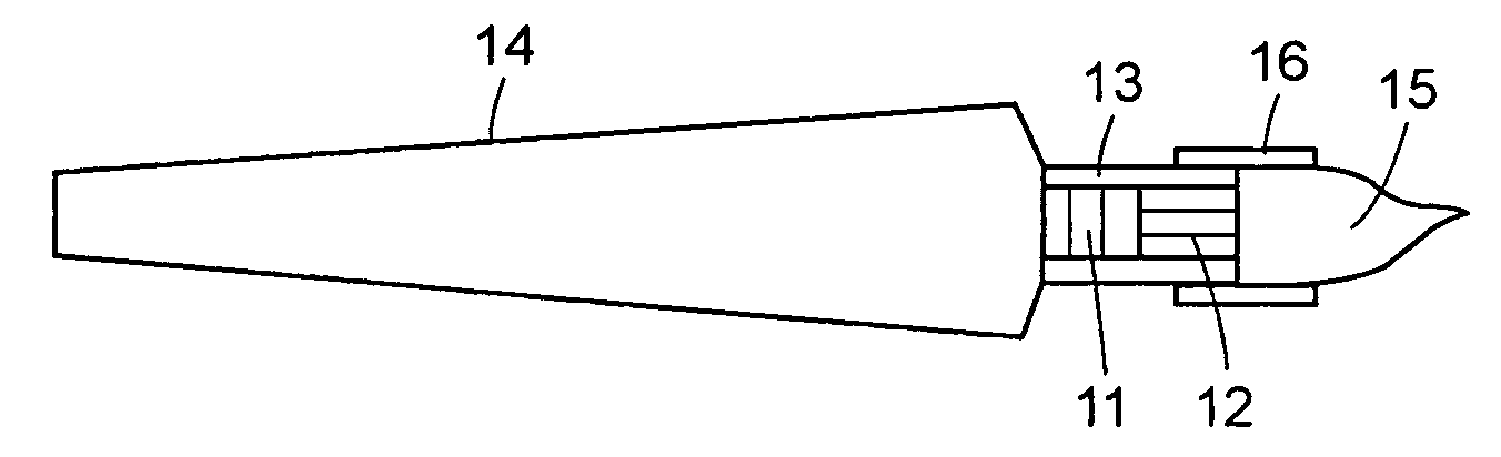
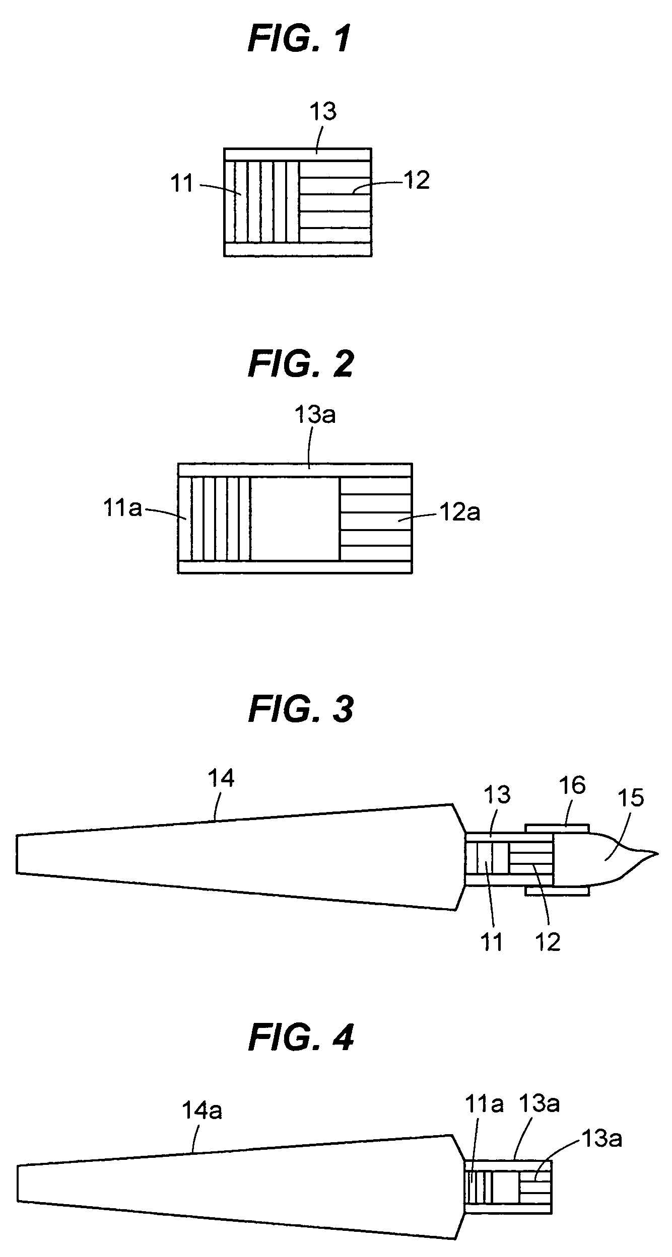
[0031]A hydrophobic reservoir 11 (density=0.4 g / cc, 5.5 OD×3 mm) and a hydrophilic reservoir 12 of various lengths (both are from Filtrona, Colonial Heights, Va.) were connected together using a Tigon tubing. The reservoir 11, 12 combination was connected to the ink barrel 14 of a color brush with the hydrophobic 11 side facing the ink. The force applied onto the barrel body 14 to squeeze the ink out was measured. Table 1 depicts the result of this experiment.

[0032]

TABLE 1The pressure (force) needed to effect fluid flow across reservoirs / filters 11, 12 of various lengths of the hydrophilic segment.Force RequiredLength of Hydrophilic reservoirs (12) in mm(kg)358Initial Flow to tip (kg)1.21.251.3To have the first drop of1.21.251.3water dripping out

example 2

[0033]Color brushes 15 incorporating hydrophobic reservoirs 11 (5.5 mm OD×3 mm) of various densities (0.4, 0.344, 0.289 g / cc) were prepared. A hydrophilic reservoir 12 was not included in this test. The force applied onto the barrel body 14 to squeeze the ink out was measured for these color brushes. Table 2 depicts the result of this experiment.

[0034]

TABLE 2The pressure (force) needed to effect fluid flow across hydrophobicreservoir / filter 11 of various densities.Density of HydrophobicForce Requiredreservoirs (11) in gram per cc(kg)0.40.3440.289Initial Flow to tip (kg)2.80.890.59To have the first drop of3.31.491.21water dripping out

[0035]Thus, the layer force required for the structure with the hydrophobic filter element 12 only (i.e., without the hydrophilic element) illustrates the benefit of controlled flow with reduced pressure provided by the hydrophobic / hydrophilic filter combination 11, 12 of this disclosure.


PUM


Abstract

A fluid control system for writing instruments, correction fluid dispensers and self contained paint brush and paint reservoirs is disclosed. The fluid control system includes two filters or reservoirs, including a hydrophobic filter / reservoir and a hydrophilic filter / reservoir. The hydrophobic and hydrophilic elements may be spaced adjacent to and in abutting engagement with each other or a gap or space may be disposed therebetween. The hydrophobic element is disposed adjacent to the fluid reservoir (i.e., ink, correction fluid, paint reservoir or other water based fluid) and the hydrophilic element is disposed adjacent to the applicator tip or brush.

Description

CROSS-REFERENCE TO RELATED APPLICATION[0001]This application claims the benefit under 35 U.S.C. § 119(e) of U.S. Provisional Patent Application Ser. No. 60 / 496,301, filed Aug. 19, 2003, the disclosure of which is incorporated herein by reference.BACKGROUND[0002]1. Technical Field[0003]A substitute for a mechanical valve with moving parts for fluid dispensing instruments such as writing instruments and painting instruments is disclosed. More specifically, instead of a mechanical valve such as a ball valve, needle valve, or duck bill valve, a combination of filters is substituted for a mechanical valve. Still more specifically, a combination of hydrophobic and hydrophilic filters are used to control the flow of ink, paint correction fluid or any other water based fluids from a flexible barrel reservoir to the tip, brush or applicator of the instrument. Still more specifically, a hydrophobic filter media is disposed between the fluid supply and a hydrophilic filter media. The hydrophil...

Claims


Application Information

Patent Timeline
Patent Type & Authority Patents(United States)
IPC IPC(8): A46B11/04A47L13/22A46B11/00
CPCA46B11/0041A46B11/0079A46B11/0082B43K5/04B43K5/18B43K8/04B43L19/0018B43L19/0068B43M11/06A46B11/0013A46B2200/205
Inventor KWAN, WING SUM VINCENTDAVIES-SMITH, LEIGHTON
Owner SANFORD LP
Why Eureka
Try Eureka