
Plug-in wiring structure of optoelectronic device

a technology of optoelectronic devices and wiring structures, which is applied in the direction of contact members penetrating/cutting insulation/cable strands, printed circuits, connections, etc., can solve the problems of reworking the whole package of devices over the cell plate to retrieve the loss, and the outside assembly and maintenance are very difficult, so as to achieve simple assembly and disassembly of the bus straps. , the effect of zero drawing for

Inactive Publication Date: 2009-01-27
LEATEC FINE CERAMICS
View PDF9 Cites 4 Cited by
  • Summary
  • Abstract
  • Description
  • Claims
  • Application Information

AI Technical Summary

Benefits of technology

[0009]The primary objective of this invention is to provide a plug-in wiring structure of the photovoltaic device, which may be embodied without any tool and with zero drawing force, so as to overcome the disadvantages of conventional technologies and achieve simpler assembly and disassembly of the bus straps.
[0010]Another objective of this invention is to provide a plug-in wiring structure of the photovoltaic device, which has multiple-point connection in the contact between the bus straps and the wiring terminals, so as to reduce the contact impedance and decrease the power loss.
[0011]Yet a further objective of this invention is to provide a plug-in wiring structure of the photovoltaic device, of which the wiring terminals are large-area copper-made terminals, so as to enhance the performance of heat dissipation.

Problems solved by technology

Thus, it involves even unfavorable disassembly and replacement since disassembly can be performed only with an electric iron, so that outdoor assembly and maintenance are very difficult.
Second, there are defects in the clip spring for press-connection so that the connection area between the clip spring and the bus strap amounts to the cross-sectional area of the clip material merely and a relatively small contact area is formed there between.
Furthermore, this sectional contact in the structure (as having been known in the above description), which can make the bus strap broken under pressure and result in rework of the whole package of devices over the cell plate to retrieve the loss.

Method used


Image

  • Plug-in wiring structure of optoelectronic device
  • Plug-in wiring structure of optoelectronic device
  • Plug-in wiring structure of optoelectronic device

Examples


Embodiment Construction

[0021]For the purpose of further appreciation and realization of the shape, features and functions of the inventive structure, a more preferable embodiment is set forth and described in details accompanying the drawings.

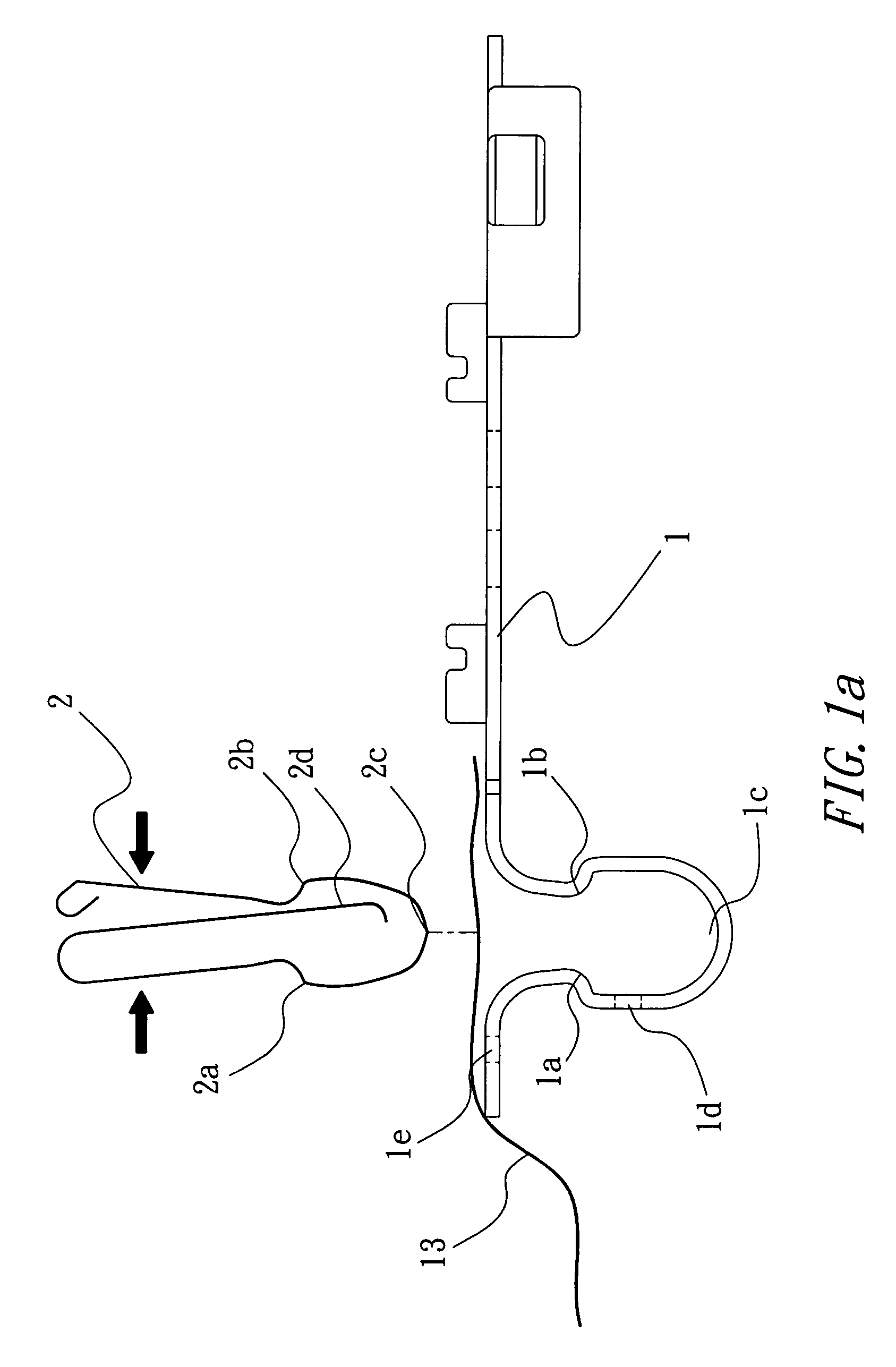
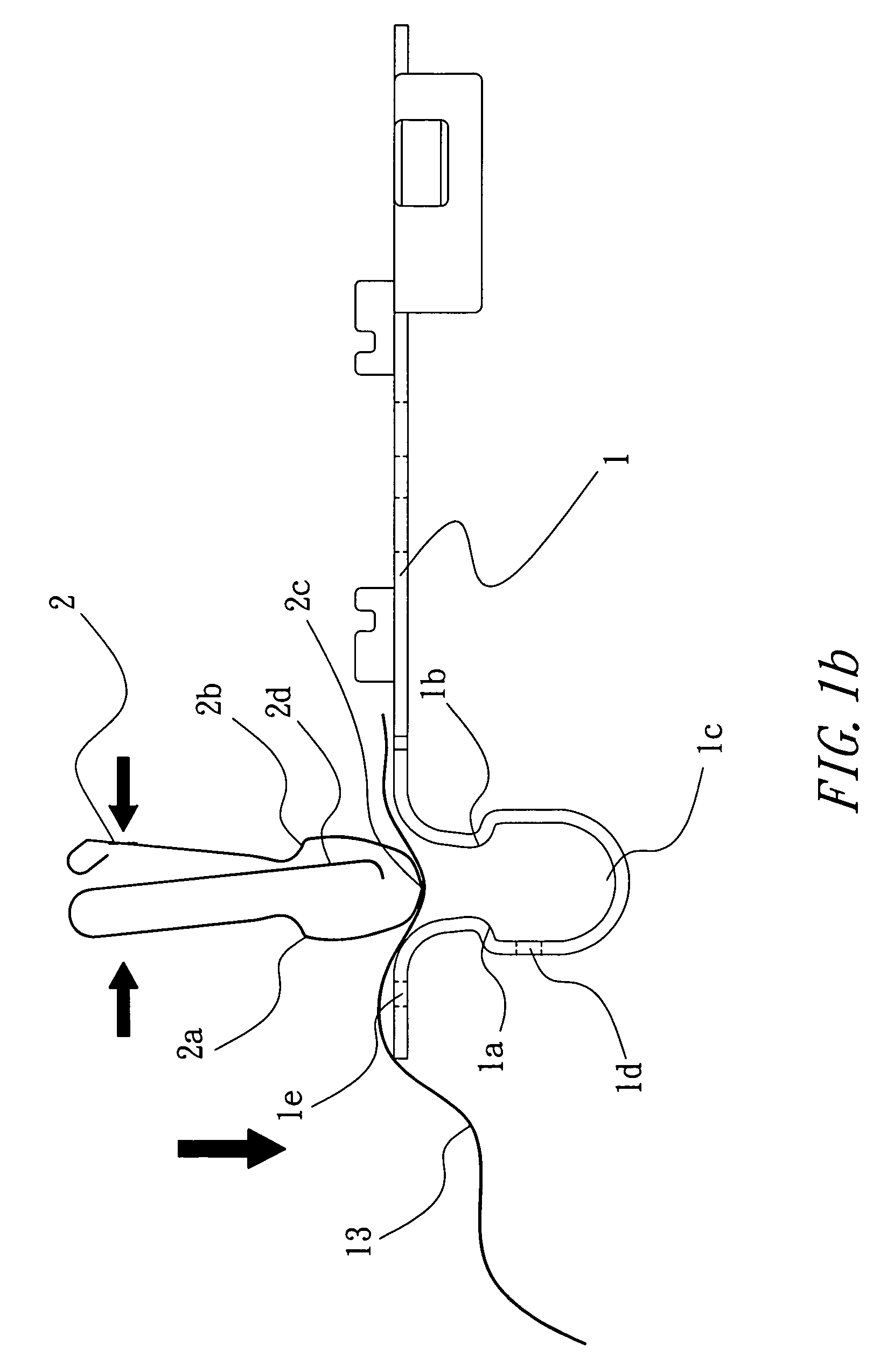
[0022]Refer to FIG. 1a, which shows an embodiment of the plug-in wiring structure of the photovoltaic device. A wiring terminal 1 has a wiring hole 1e, through which a bus strap 13 may pass. The bus strap 13 may lie over the wiring terminal 1 as well. The wiring terminal 1 has a locking hole 1d for fixing the wiring terminal 1. The wiring terminal 1 has a U-shaped construction disposed at the front end thereof and has two locking points 1a and 1b and a curved bottom 1c disposed in the U-shaped construction, for locking a clip spring thereto. The clip spring is a U-shaped clip spring 2 with locking points. The U-shaped clip spring 2 has locking points 2a and 2b, a curved bottom 2c and a side hook 2d extending to tightly contact an opposite side portion 2e, so that the...


PUM


Abstract

The present invention relates to a plug-in wiring structure of the photovoltaic device, which is applicable to thin-strap connection in electric or electronic apparatuses, such as the output connection of copper-made thin bus straps in a package of solar cell plates. The present invention is characterized in a specialized design that includes a U-shaped clip spring with multiple turnings and a U-shaped terminal so as to have a fixed connection of a thin-strap object. According to the inventive connection, the work procedure of packaging solar cell plates can be simplified and high reliability can be achieved in that it is free from tool for disassembly and can be performed with zero drawing force. The present invention is especially applicable to the package of large-scaled photovoltaic generation cell plates having output through multiple bus straps.

Description

BACKGROUND OF THE INVENTION[0001]1. Field of the Invention[0002]The present invention relates to a plug-in wiring structure of the photovoltaic device.[0003]2. Descriptions of the Related Art[0004]Since the voltage of a single solar cell is relatively low, in the application of solar photovoltaic generation, multiple cells may be connected in certain combination and then packaged to form a photovoltaic device for use in various severe environmental conditions. Regular photovoltaic components, or solar-cell components, are composed of packaging material, a solar-cell serial (parallel) set and a wiring structure. Photovoltaic devices may be connected serially or parallel in certain combination to form a photovoltaic array and, with other auxiliary control apparatuses, form a solar generation station. From the package of the photovoltaic components, there are multiple copper-made thin bus straps introduced to the wiring structure for connection, for which conventional methods includes ...

Claims


Application Information

Patent Timeline
Patent Type & Authority Patents(United States)
IPC IPC(8): H01R12/24
CPCH01R4/48H01R12/778H01R12/592
Inventor LEE, FANG-YI
Owner LEATEC FINE CERAMICS
Learn More