Protection of an inmoulded electric appliance against explosion

an inmoulded electric appliance and explosion-proof technology, applied in the direction of casings/cabinets/drawers, cell components, casings/cabinets/drawers, etc., can solve the problems of affecting the operation of the electric appliance, the electrolyte inside the electric appliance begins to vaporize, and the vulnerability of the explosion, so as to reduce the risk of explosion, and reduce the effect of explosion

Inactive Publication Date: 2009-01-27
SALCOMP OYJ
View PDF15 Cites 1 Cited by
  • Summary
  • Abstract
  • Description
  • Claims
  • Application Information

AI Technical Summary

Benefits of technology

[0011]An objective of the invention is to provide an inmoulded or potted electric appliance with enhanced safety against cracking or exploding. An objective of the invention is also to ensure that the enhanced safety is readily applicable in many kinds of inmoulded or potted electric appliances. Additionally the invention aims at ensuring ease of manufacture and low additional cost.
[0018]The invention is based on the insight that actually only a relatively small space is needed to receive the vapour discharging from an overheated electrolytic capacitor. The danger of an explosion is worst if there is no space at all, so that even the smallest amount of pressurized vapour suffices to cause a dangerous amount of pressure. A small space that receives the first attack of discharging vapour will soften the pressure shock and slow down the increase of pressure so that electric protection mechanisms have sufficient time to operate and stop the generation of more vapour. The material of the moulded or potted part must include a deliberately formed cavity next or very near to the electrolytic capacitor, so that the cavity is the easiest and most natural place for the discharging vapour to go to.

Problems solved by technology

A problem of an inmoulded or potted electric appliance is its vulnerability to explosion under certain very improbable but still possible circumstances.
If an electrolytic capacitor 105 is subjected to overvoltage or a voltage of incorrect polarity, it may heat up so much that the electrolyte inside thereof begins to vaporize.
However, the known protective measures may be so slow to react that a significant amount of vaporized electrolyte is still formed, causing a sudden rise of internal pressure within the moulded part.
If the pressure difference between the inside and outside of the moulded or potted part becomes sufficiently large, the moulded part may crack.
The vulnerability to explosion of inmoulded or potted electric appliances becomes worse if the appliance should be made as small as possible.
Small size means thin material thickness of the moulded or potted material between the component part inside it and the outside, which in turn may lead to weaker mechanical strength and consequently to vulnerability to explosion even with relatively moderate pressure differences.
However, using a reinforcing substance increases material costs and may cause disadvantages in other aspects of the manufacturing process, like increasing the mechanical wear of moulds, causing interference in the flow of the moulding material or producing unwanted visible effects on outer surfaces.
Errors like an electrolytic capacitor assembled with incorrect polarity should reveal themselves in these tests.
However, it is impossible to make the tests so extensive that they would take into account each and every form of exceptional operational conditions.
It is also possible that a testing cycle goes so fast that an electrolytic capacitor with an internal fault does not make it to exploding before the test voltage is removed.
This solution does not solve the problem of expanding gaseous electrolyte.

Method used


Image

  • Protection of an inmoulded electric appliance against explosion
  • Protection of an inmoulded electric appliance against explosion
  • Protection of an inmoulded electric appliance against explosion

Examples


Embodiment Construction

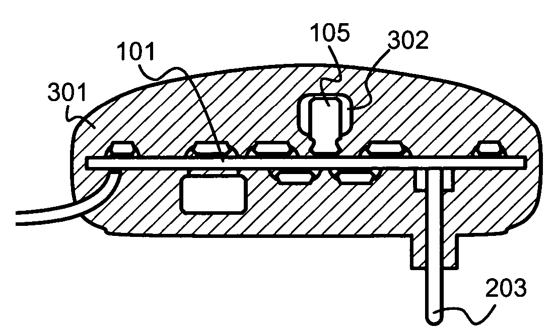
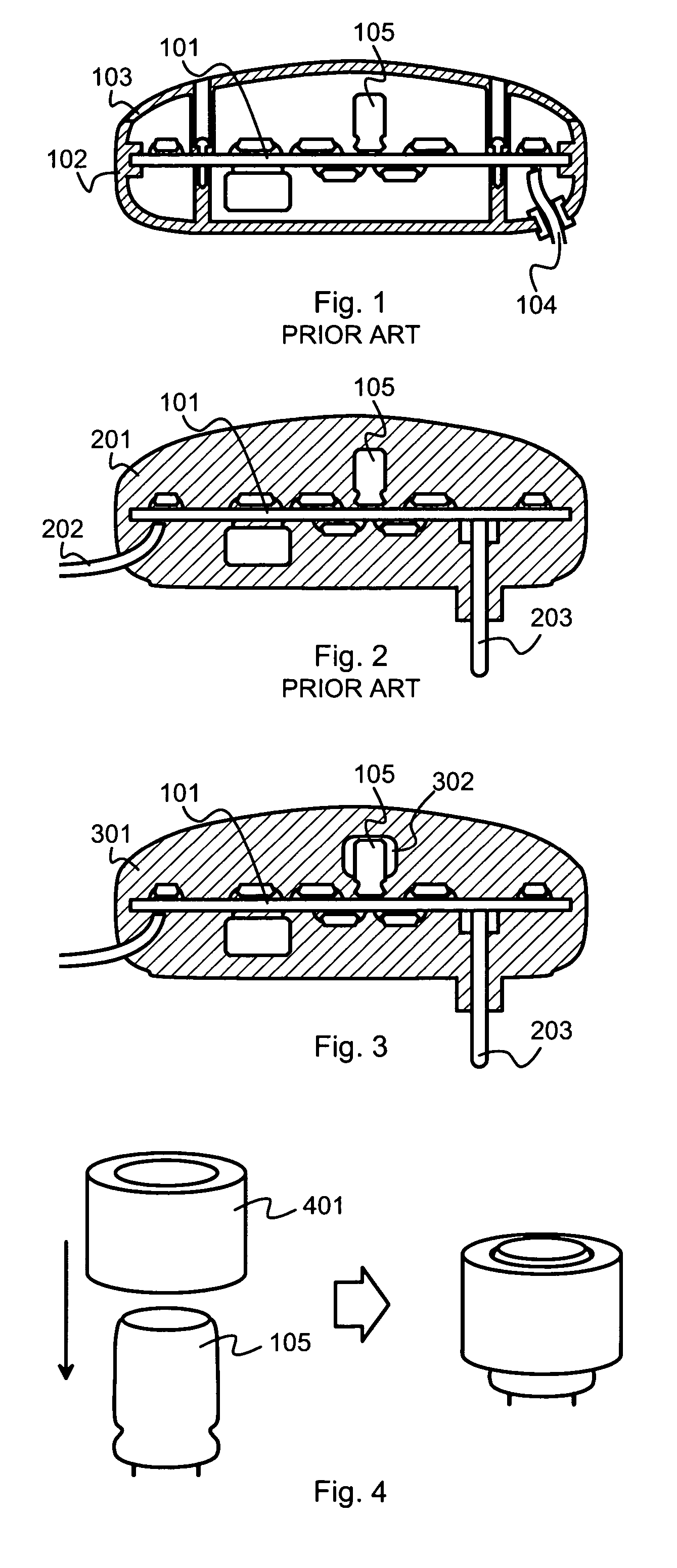
[0037]In the following description we will mainly focus on inmoulded solutions, but the same aspects of the invention are readily applicable also to potted electric appliances.

[0038]FIG. 3 illustrates schematically, in partial cross section, an electric appliance which comprises a component part 101 and a moulded part 301. Among the components of the component part 101 there is an electrolytic capacitor 105. The moulded part 301 has been moulded around the component part 101 so that the outer surface of the moulded part 301 constitutes a major part of the outer surface of the whole electric appliance. A part at which the outer surface of the electric appliance comprises something else is for example at the connector pins 203, which enable sticking the electric appliance into a wall socket like a wall plug.

[0039]Since the moulded part 301 has been moulded around the component part 101, it naturally contains an internal “cavity” of the size and shape of the component part 101. However...


PUM

PropertyMeasurementUnit
thicknessaaaaaaaaaa
elasticaaaaaaaaaa
pressureaaaaaaaaaa

Abstract

An electric appliance comprises a component part (101) that comprises electronic components, among which is an electrolytic capacitor (105). A molded part (301) is molded around the component part (101), An outer surface of the molded part (301) constitutes at least a part of the outer surface of the electric appliance. The molded part comprises a cavity (302), which contains something else than electronic components or connections between electronic components. The cavity (302) is separated from the electrolytic capacitor (105) by at most a wall the thickness of which is smaller than a mean material thickness of the molded part (301) between the component part (101) and outside of the electric appliance.

Description

CROSS REFERENCE TO RELATED APPLICATIONS[0001]This application claims priority under 35 USC §119 to Finnish Patent Application No. 20050462 filed on Apr. 29, 2005.TECHNICAL FIELD[0002]The invention concerns to the assembling and packaging of electric devices. Especially the invention relates to protecting an inmoulded electric appliance against an explosion that might result from the vaporization of part of an electronic component, especially an electrolytic capacitor.BACKGROUND OF THE INVENTION[0003]FIG. 1 is a partial cross section illustrating an exemplary prior art electric device that comprises a component part 101 and an outer cover, which in this case consists of a lower cover part 102 and an upper cover part 103. Wired connections 104 to and from the electric appliance can be made through holes in the outer cover. We assume that among the components of the component part 101 is an electrolytic capacitor 105.[0004]FIG. 2 illustrates another exemplary prior art device, which is...

Claims


Application Information

Patent Timeline
Patent Type & Authority Patents(United States)
IPC IPC(8): H01G9/00H01G9/08
CPCH01G9/08Y10T29/417H05K5/065H01G9/12
Inventor LEHTONEN, MIKKOHAGSTROM, MARKO
Owner SALCOMP OYJ
Why Eureka
Try Eureka