Band stop filter

Inactive Publication Date: 2009-01-27
INTEL CORP
View PDF7 Cites 5 Cited by
  • Summary
  • Abstract
  • Description
  • Claims
  • Application Information

AI Technical Summary

Problems solved by technology

The transition band of the filter must naturally be narrower than the specified duplex spacing, which means that the stop attenuation cannot be freely increased.
One drawback of the filter according to FIG. 1 is a relatively large number of structural parts in the transmission line structure, which increases the production costs.
A large number of parts also means nume

Method used


Image

  • Band stop filter
  • Band stop filter
  • Band stop filter

Examples


Embodiment Construction

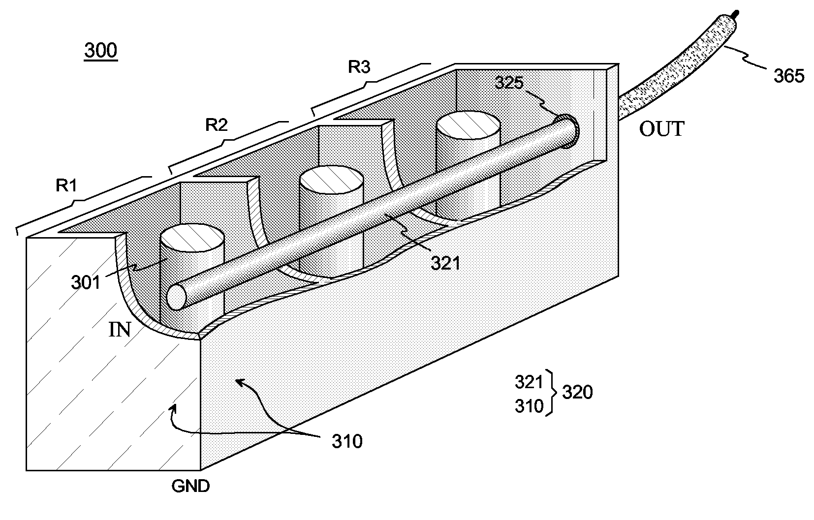
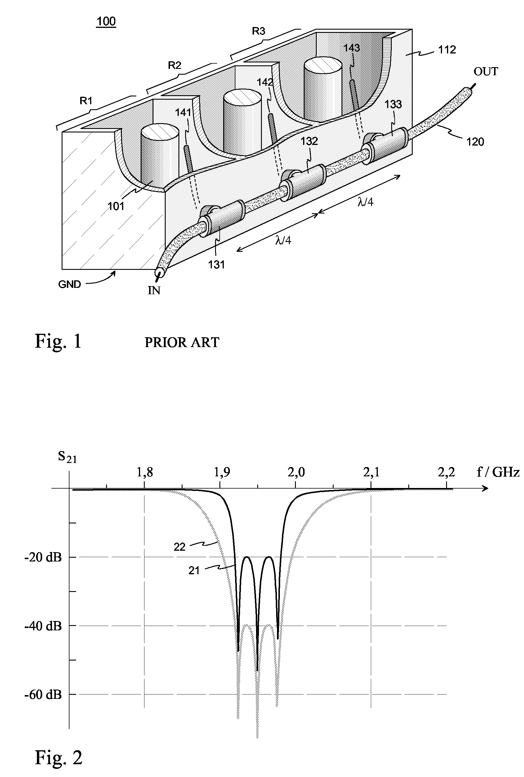
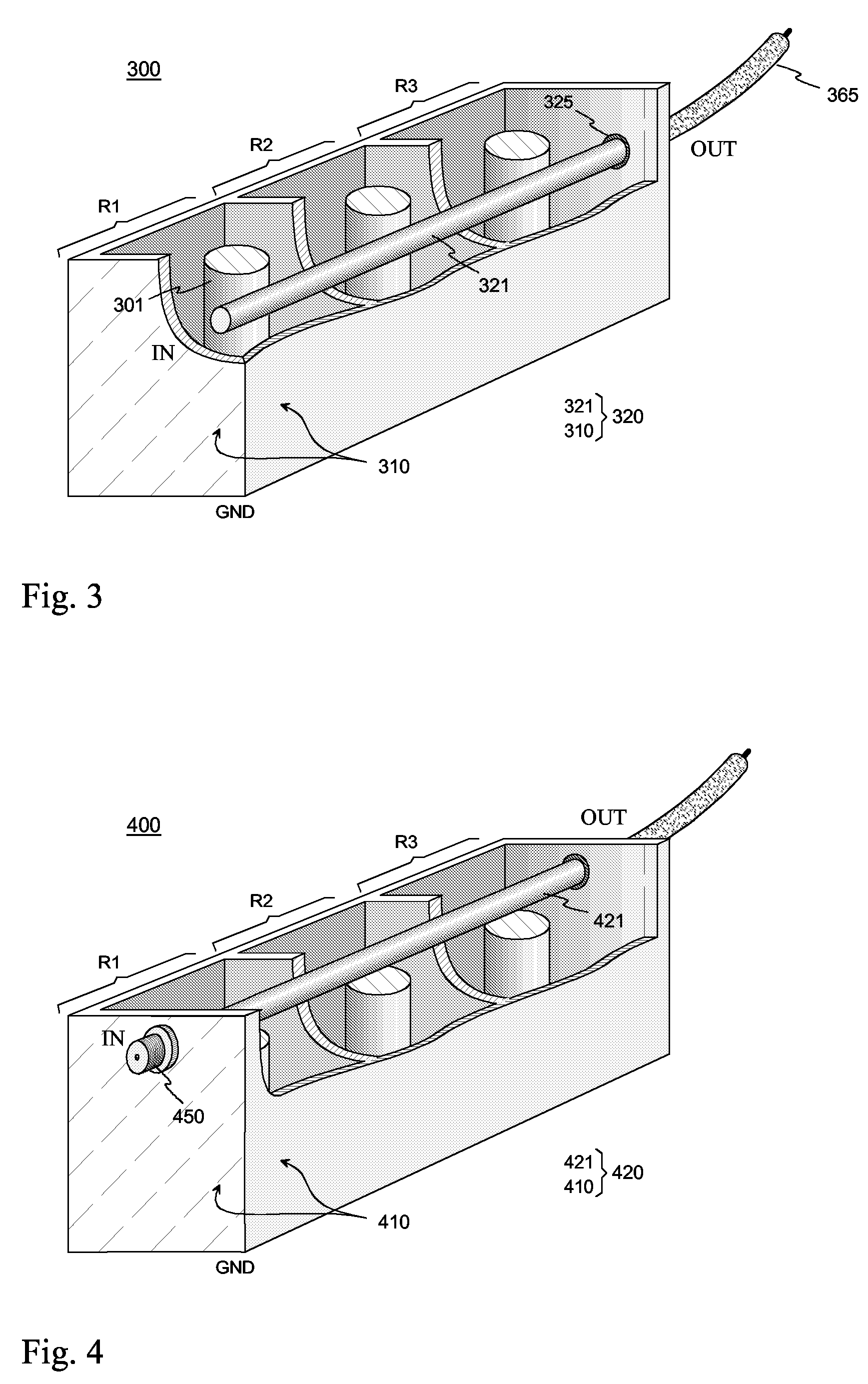
[0017]By way of overview and introduction, a band stop filter structure comprises a transmission line and coaxial resonators electromagnetically coupled parallel with it, the natural frequencies of the resonators differing from each other slightly. The resonators form a unitary conductive resonator housing, the inner space of which has been divided into resonator cavities by conductive partition walls. The center conductor of the transmission line is placed inside the resonator housing so that it runs through all the resonator cavities, and the housing functions as the outer conductor of the transmission line at the same time. The resonator cavities are thus a part of the cavity of the transmission line. When an electromagnetic field of the same frequency as the natural frequency of a resonator occurs in the transmission line, the resonator in question starts to oscillate, causing the field to reflect back towards the feeding source. The strength of the resonance and the width of it...


PUM


Abstract

A band stop filter comprises a transmission line with center and outer conductors, and coaxial resonators. The outer conductor forming a unitary conductive housing with an inner space divided by conductive partition walls into resonator cavities. Each of the resonator cavities contains at least one of the coaxial resonators, wherein each of the coaxial resonators separately has an electromagnetic coupling to the transmission line. The coupling arranged by a coupling element to form an attenuation peak in the a response curve of the filter, where the natural frequencies of the coaxial resonators differ from each other to shape the response curve of the filter. The transmission conductor is located inside the housing, running through openings in the partition walls across all the resonator cavities. The housing is the outer conductor of the transmission line, and a portion of the transmission conductor in a resonator cavity is the coupling element.

Description

CLAIM OF PRIORITY[0001]This patent application claims the benefit of priority, under 35 U.S.C. § 365, of International Application No. PCT / FI2005 / 050140, filed Apr. 29, 2005, titled “Band Stop Filter,” which published in the English language on Nov. 17, 2005, and also claims the benefit of priority, under 35 U.S.C. § 119, of Finland Application No. 20040672 filed May 12, 2004. The entire disclosures of each are hereby incorporated herein by reference in their entirety.FIELD OF THE INVENTION[0002]The invention relates to a band stop filter implemented by coaxial resonators for filtering antenna signals particularly in base stations of mobile communication networks.BACKGROUND OF THE INVENTION[0003]In bidirectional radio systems of mobile communication networks, the transmitting and receiving bands are relatively close to each other. In the full duplex system, in which signals are transferred in both directions simultaneously, it must be especially ensured that a transmitting of relati...

Claims


Application Information

Patent Timeline
IPC IPC(8): H01P1/205H01PH01P1/20H01P1/209
CPCH01P1/209H01P1/2053
Inventor PUOSKARI, JUKKAALA-KOJOLA, JOUNI
Owner INTEL CORP
Why Eureka
Try Eureka