Limiter for controlling overvoltage and RFID tag having the same

a technology of limiter and overvoltage, which is applied in the direction of burglar alarm mechanical actuation, burglar alarm by hand-portable object removal, etc., can solve the problems of limiter not being able to control a voltage below the threshold voltage, the driving elements of the rfid tag can malfunction or be damaged, etc., to achieve minimize the leakage current, maximize the leakage current, and improve the yield of products

Active Publication Date: 2009-01-27
SAMSUNG ELECTRONICS CO LTD
View PDF5 Cites 18 Cited by
  • Summary
  • Abstract
  • Description
  • Claims
  • Application Information

AI Technical Summary

Benefits of technology

[0013]The present invention provides a limiter for controlling an overvoltage to maximize leakage current according to the overvoltage.
[0030]As can be appreciated from the above description, the limiter of the RFID tag includes the first limiter part and the second limiter part including at least one limit diode with the threshold voltage lower than that of the elements in the first limiter part. Accordingly, if the overvoltage is supplied, the limiter can maximize the leakage current, and if a low voltage lower than the reference voltage is supplied, the limiter can minimize the leakage current. As a result, the RFID tag can prevent the RFID driving part from being damaged due to the overvoltage. In addition, the RFID tag can normally operate regardless of the intensity of the driving voltage input from the RFID reader, so that the yields of products can improve.

Problems solved by technology

If the overvoltage is supplied to the RFID tag, the driving elements in the RFID tag can malfunction or be damaged.
However, in general, the threshold voltage of the MOSFET is about 0.8 V, so the limiter can not control a voltage below the threshold voltage.

Method used


Image

  • Limiter for controlling overvoltage and RFID tag having the same
  • Limiter for controlling overvoltage and RFID tag having the same
  • Limiter for controlling overvoltage and RFID tag having the same

Examples


Embodiment Construction

[0036]Hereinafter, exemplary embodiments of the present invention will be described in detail with reference to the accompanying drawing figures.

[0037]In the following description, same drawing reference numerals are used for the same elements even in different drawings. The matters defined herein are described at a high-level of abstraction to provide a comprehensive yet clear understanding of the invention. It is also to be noted that it will be apparent to those ordinarily skilled in the art that the present invention is not limited to the description of the exemplary embodiments provided herein.

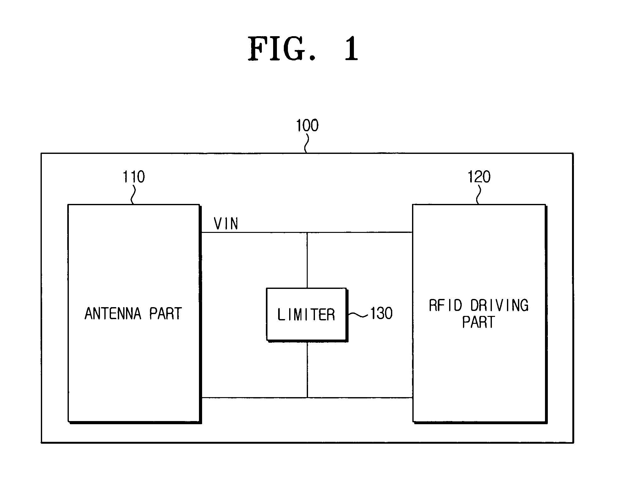
[0038]FIG. 1 is a block diagram showing the configuration of an RFID tag according to an exemplary embodiment of the present invention.

[0039]Referring to FIG. 1, the RFID tag 100 includes an antenna part 110, an RFID driving part 120 and a limiter 130.

[0040]To be specific, the antenna part 110 transmits and receives data to / from an RFID reader (not shown) wirelessly. That is, the antenna ...


PUM


Abstract

A limiter for controlling an overvoltage and an RFID tag having the same are provided. The limiter includes a first limiter part and a second limiter part serially connected to the first limiter part. The second limiter part has at least one limit diode whose threshold voltage is lower than that of elements in the first limiter part. Accordingly, if an overvoltage is input, the limiter can maximize the input current drop so that the limiter can maximize the leakage voltage. As a result, the RFID tag can prevent the RFID driving part from being damaged due to the overvoltage. In addition, the RFID tag can normally operate regardless of the intensity of the driving voltage input from the RFID reader, so that the yields of products can improve.

Description

CROSS-REFERENCE TO RELATED APPLICATIONS[0001]This application claims priority from Korean Patent Application No. 10-2005-0130759, filed Dec. 27, 2005 in the Korean Intellectual Property Office, the entire contents of which are incorporated herein by reference.BACKGROUND OF THE INVENTION[0002]1. Field of the Invention[0003]The present invention relates to a limiter for controlling an overvoltage and a radio frequency identification (RFID) tag having the same. More particularly, the present invention relates to a limiter for controlling an overvoltage to protect driving elements of the RFID tag by limiting an overvoltage received from an RFID reader.[0004]2. Description of the Related Art[0005]An RFID system is an automatic identification and data capture (ADC) technology using a radio frequency. The RFID system consists of an RFID reader and an RFID tag communicating with each other.[0006]Specifically, the RFID reader transmits an electromagnetic wave of a certain frequency band and ...

Claims


Application Information

Patent Timeline
Patent Type & Authority Patents(United States)
IPC IPC(8): G08B13/14
CPCG06K19/0723G06K19/077G06K19/07G06K19/073
Inventor SONG, IL-JONGMIN, YOUNG-HOONYOON, CHOL-SUSHIM, DONG-SIK
Owner SAMSUNG ELECTRONICS CO LTD
Why Eureka
Try Eureka