Control circuit of a bistable permanent magnet operating mechanism

a control circuit and operating mechanism technology, applied in mechanical devices, valves, relays, etc., can solve the problems of substantial action noise and electricity consumption, high noise of switch-on, and relatively high instantaneous closing speed, so as to reduce the relatively high running speed of components, prolong the service life of components, and reduce the noise of switch-on action.

Inactive Publication Date: 2009-01-27
WANG GUANGSHUN
View PDF3 Cites 26 Cited by
  • Summary
  • Abstract
  • Description
  • Claims
  • Application Information

AI Technical Summary

Benefits of technology

[0009]A) Reducing the relatively high running speed of the components during early switch-on period, so as to reduce the noise of switch-on action and prolong the service life of the components.
[0010]B) Increasing the instantaneous opening speed during the initial switch-off period, so as to reduce occurrence of switch-off voltaic arc.
[0011]C) Fully using two coils in the bistable permanent ma

Problems solved by technology

However, in practice, it is found that during operation, though switch-off/switch-on may be achieved if applying pulses to switch-off coil and switch-on coil respectively, the action noise and electricity consumption may be substantial.
Such a permanent magnet op

Method used


Image

  • Control circuit of a bistable permanent magnet operating mechanism
  • Control circuit of a bistable permanent magnet operating mechanism
  • Control circuit of a bistable permanent magnet operating mechanism

Examples


Embodiment Construction

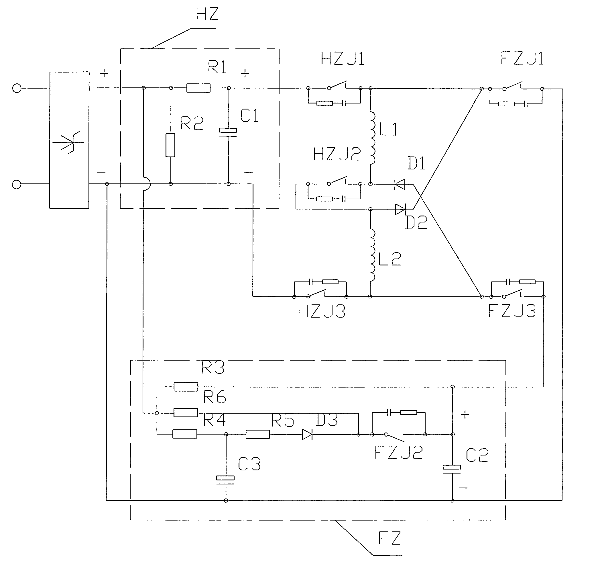
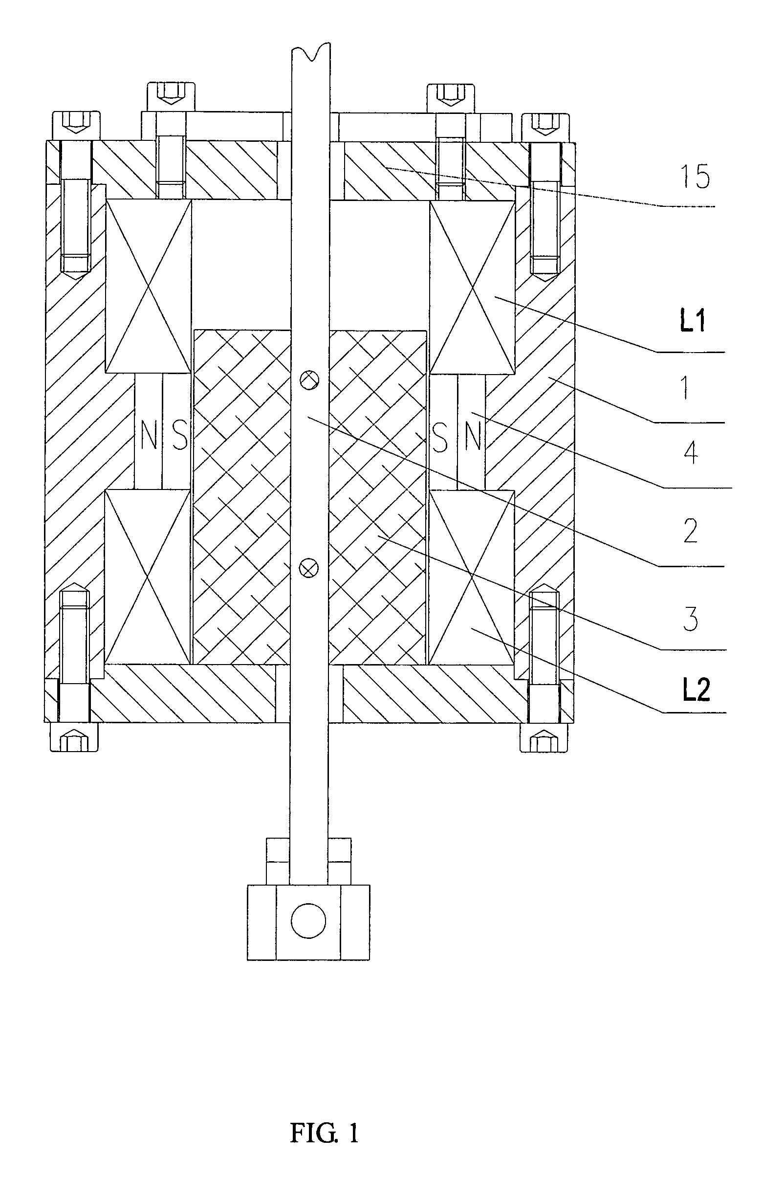
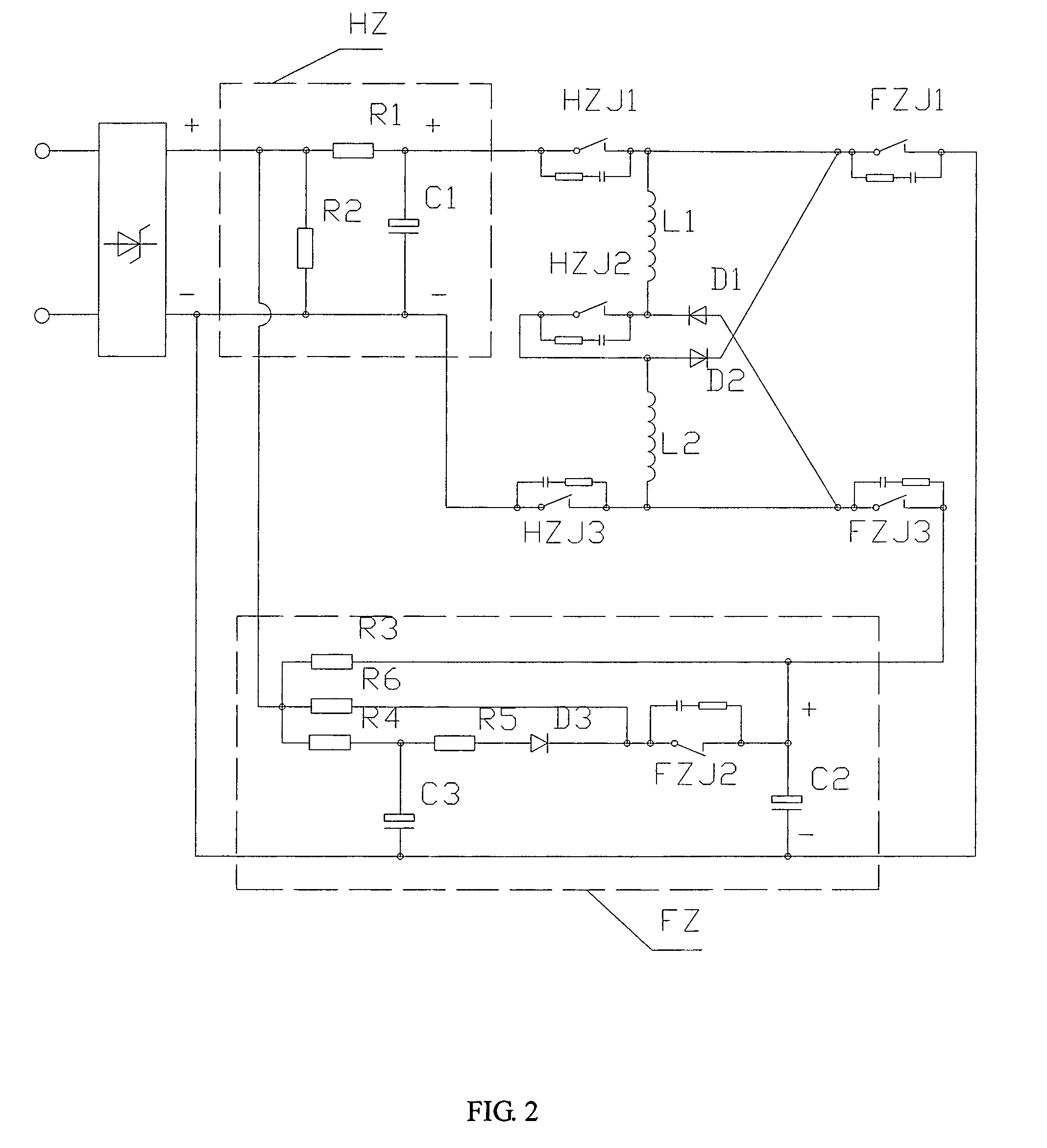
[0015]As shown in the drawings, a control circuit of a bistable permanent magnet operating mechanism of the present invention includes a permanent magnet operating mechanism, and a pulse signal control circuit connected on pulse coils of the permanent magnet operating mechanism. As shown in FIG. 1, housing 1 of the permanent magnet operating mechanism has an output shaft 2 therein. The output shaft 2 extends out through end covers 15 on both ends of the housing 1, in which the front end connects to a performing mechanism through a link pin, and the rear end securely connects to an end cap 9. The housing 1 and end covers 15 are made of conductive magnetic ferro-material. An anti-magnetic bush is mounted onto the contact region of the output shaft 2 and housing 1. The mid-section of output shaft 2, located in the housing 1, has a core 3 securely mounted thereto. The outer side of the core 3 has a permanent magnet 4. The permanent magnet 4 and the housing 1 are securely connected. A fi...


PUM


Abstract

The present invention relates to an automatic controlled operating mechanism, in particular, relates to a control circuit of a bistable permanent magnet operating mechanism. The control circuit comprises a permanent magnet operating mechanism and a pulse signal control circuit connected to pulse coils of the permanent magnet operating mechanism. The pulse signal control circuit comprises a switch-off energy storage circuit, a switch-on energy storage circuit, a switch-off contact switch, and a switch-on contact switch. With the switch-off contact switch and switch-on contact switch, the pulse coils of the permanent magnet operating mechanism are connected in the circuit in such a way that they are in series connection for switch-on and in parallel connection for switch-off. This reduces the relatively high running speed in earlier switch-on period, to reduce switch-on noise and prolong the service life. In addition, this increases the instantaneous opening speed in the initial switch-off period, to reduce generation of switch-off voltaic arc. By using the two coils in the bistable permanent magnet operating mechanism, raw material can be saved, the mechanism volume can be reduced, and the failure rate can be lowered.

Description

FIELD OF INVENTION[0001]This invention relates to an automatic controlled operating mechanism. In particular, it relates to a control circuit of a bistable permanent magnet operating mechanism.BACKGROUND OF THE INVENTION[0002]Permanent magnet operating mechanism is a mechanical device that uses pulse-electromagnetic force to conduct state conversion, and uses permanent magnet force to facilitate action and maintain state. For example, CN patent No. ZL98220417.5, entitled “A Permanent Magnet Operating Mechanism for Vacuum Switch”, owned by this Applicant, discloses such a permanent magnet operating mechanism. It includes an output shaft, a fixed core on the output shaft, a permanent magnet disposed outside the core, and an impulse coil placed on outside of each end of the permanent magnet respectively. The output shaft extends out from the center of the two impulse coils. The permanent magnet operating mechanism has the features of prompt action, automatic maintaining stabilization o...

Claims


Application Information

Patent Timeline
IPC IPC(8): H01H9/00H01H47/00F16K31/08
CPCH01H33/6662H01H47/226
Inventor WANG, GUANGSHUN
Owner WANG GUANGSHUN
Why Eureka
Try Eureka