Dual anode capacitor with internally connected anodes

a dual anode capacitor and anode technology, applied in the field of capacitors, can solve the problems of reducing battery capacity, misalignment of electrodes, and long time for stacking electrodes and electrode units

Active Publication Date: 2009-01-27
WILSON GREATBATCH LTD
View PDF24 Cites 73 Cited by
  • Summary
  • Abstract
  • Description
  • Claims
  • Application Information

AI Technical Summary

Benefits of technology

[0018]It is an object of this invention to provide a dual anode capacitor connected by a common lead within the capacitor casing, thereby eliminating the need for multiple feedthroughs being provided within the capacitor.

Problems solved by technology

This leads to a longer period of time for stacking the electrodes and the electrode unit, or requires it to use a high precision apparatus for alignment.
It prevents any significant motion of these electrodes relative to each other, which could misalign the electrodes and reduce the battery capacity.
It is apparent that were Kajiura et al. to use individual wire connectors between the anode and / or cathode plates in lieu of the flexible strip shaped regions, the ability to easily align the anodes and cathodes in a stacked configuration during battery fabrication, and to maintain the critical alignment during battery use would be lost.
Such a battery would thus be rendered unsuitable for its intended purpose.
For each of these fabrication methods, the use of intermittent current collector strips connected by wire bridges would result in additional challenges.
Sintering requires uniform heat transfer, which is problematic with a discontinuous substrate.
The coating of small substrate surfaces that are wire bonded either before or after coating is considerably more difficult than coating a continuous strip of material.
Thus, the Kajiura et al. patent does not show or suggest an electrical energy storage device in which the individual anode or cathode plates are connected by a wire or by a narrow strip of material having opposed planar surfaces that do not extend laterally beyond edges of the anode or cathode plates.
Additionally, none of the references cited above disclose an electrical energy storage device including at least two anodes that are connected to a common terminal within the capacitor casing.

Method used


Image

  • Dual anode capacitor with internally connected anodes
  • Dual anode capacitor with internally connected anodes
  • Dual anode capacitor with internally connected anodes

Examples


Embodiment Construction

[0044]For a general understanding of the present invention, reference is made to the drawings. In the drawings, like reference numerals have been used throughout to designate identical elements.

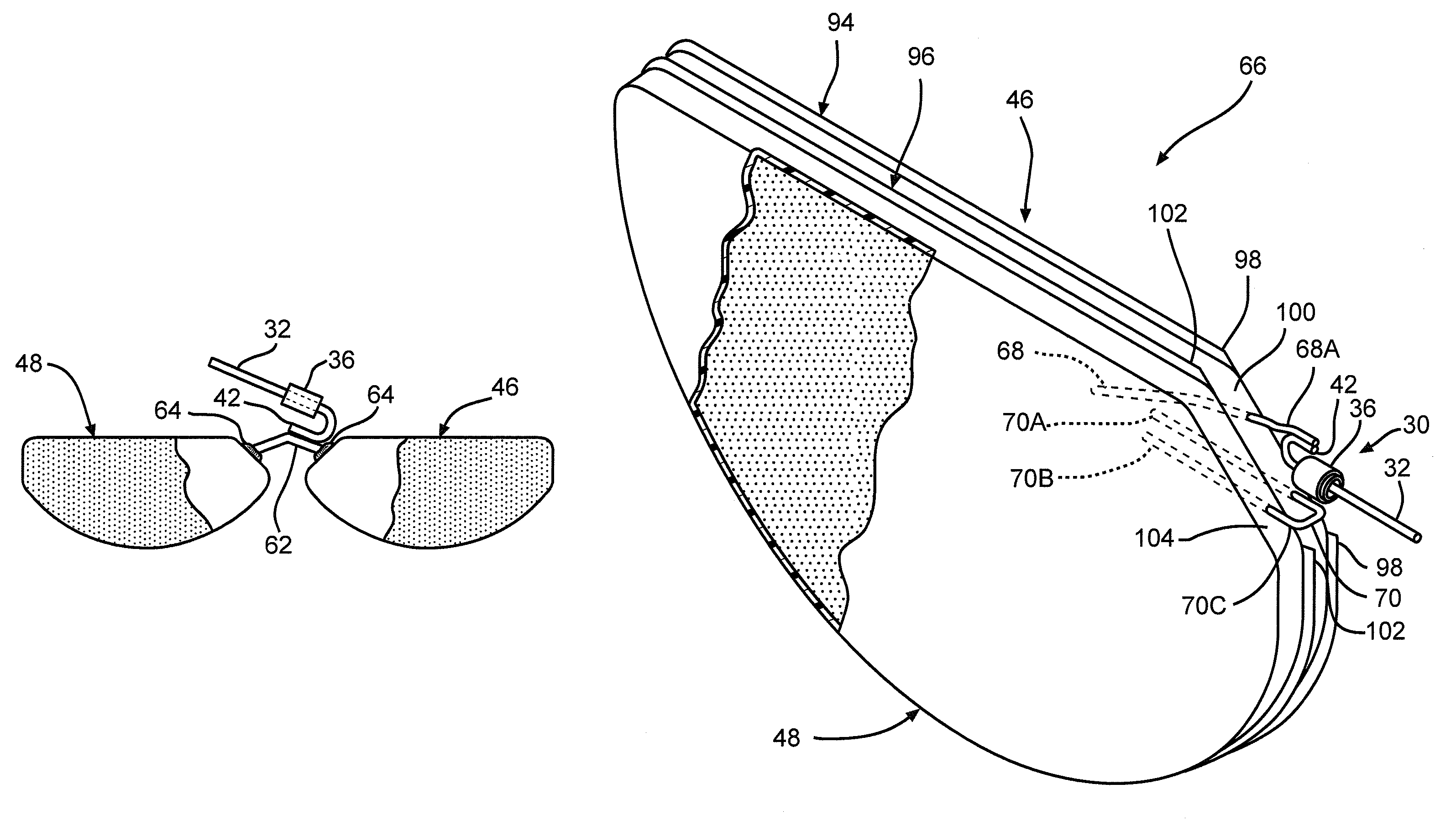
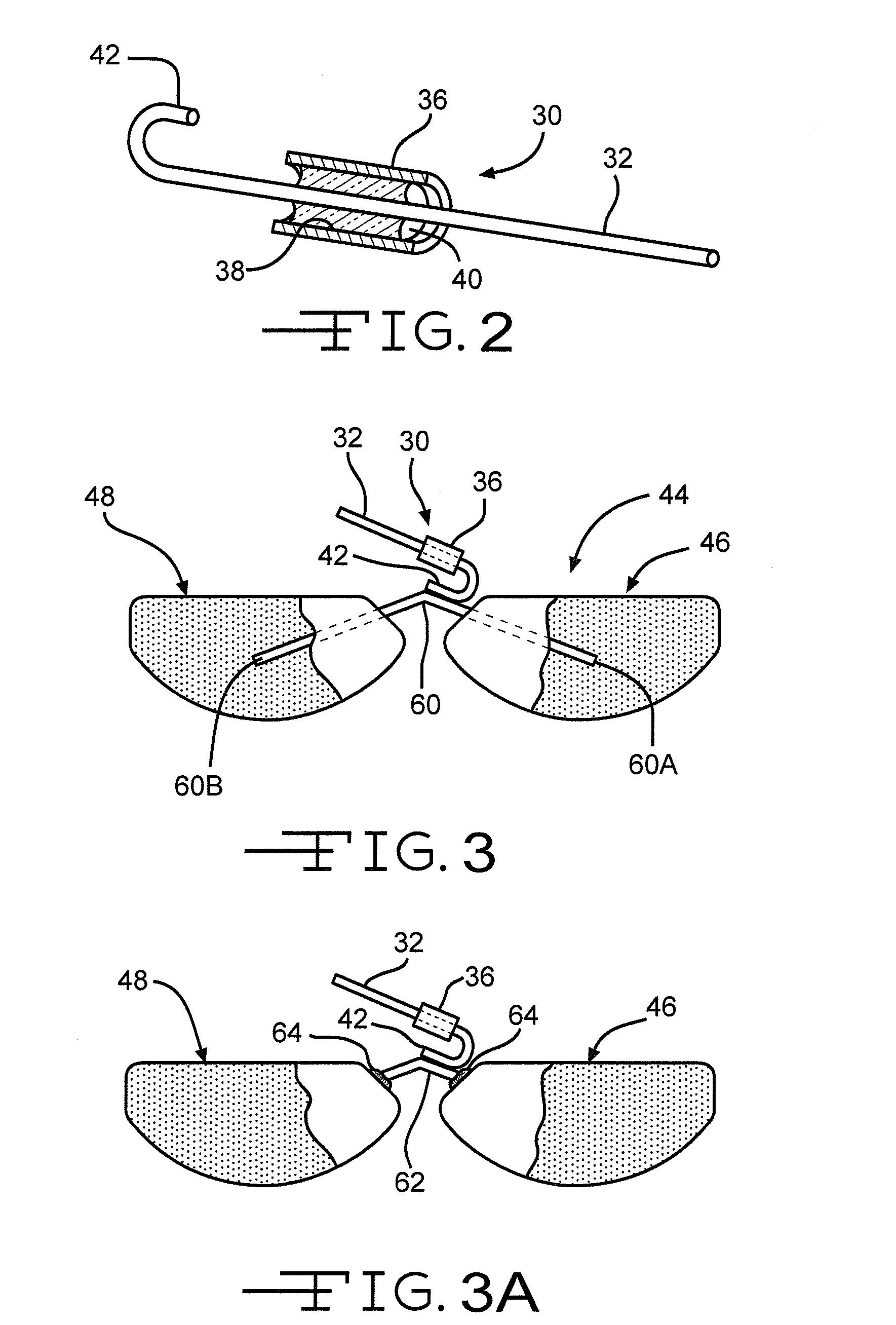
[0045]As used herein, the term “wire” refers to a metal structure in the form of a relatively slender rod that does not extend laterally beyond the surrounding edge formed between the opposed major faces of an anode pellet.

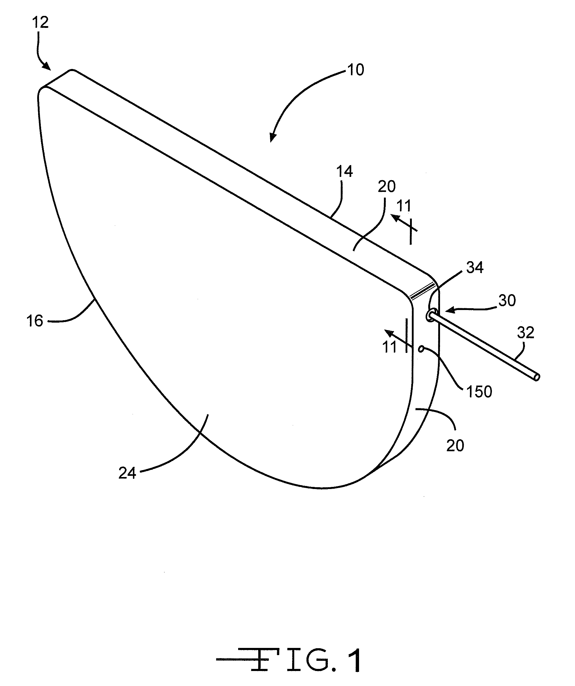
[0046]FIG. 1 is a perspective view of a capacitor according to the present invention. The capacitor 10 comprises at least two anodes of an anode active material and a cathode of a cathode active material housed inside a hermetically sealed casing 12. The capacitor electrodes are operatively associated with each other by a working electrolyte (not shown) contained inside the casing. The anodes, cathode, and electrolyte of capacitor 10 will be described in detail hereinafter.

[0047]As particularly shown in FIGS. 1, 9 and 10, the casing 12 is of metal material comprising first ...


PUM

PropertyMeasurementUnit
electrical currentaaaaaaaaaa
thicknessaaaaaaaaaa

Abstract

A capacitor a casing of first and second casing members, a feedthrough electrically insulated from the casing and extending there from, first and second anodes electrically connected to each other within the casing, a cathode, and an electrolyte is described. The first anode is electrically connected in parallel to the second anode by a first anode wire having opposite ends contacting the respective first and second anodes. A feedthrough wire extending outside the casing and electrically isolated there from is electrically connected to the first anode wire intermediate the first and second anodes. The cathode is disposed between the first and second anodes.

Description

BACKGROUND OF THE INVENTION[0001]1. Field of the Invention[0002]The present invention generally relates to a capacitor and, more particularly, to a capacitor containing at least two anodes that are connected to a common terminal within the capacitor casing.[0003]2. Description of Related Art[0004]As more and more medical applications are investigated and implemented to aid and assist the human body, devices needed to deliver the desired therapy are becoming increasingly more sophisticated, both functionally and in terms of their structural makeup. Modern implantable devices require power sources that are smaller in size, but powerful enough to meet the therapy requirements. For example, a cardiac defibrillator has a battery powering circuits performing such functions as, for example, the heart sensing and pacing functions. This requires electrical current of about 1 microampere to about 100 milliamperes. From time-to-time, the cardiac defibrillator may require a generally high rate,...

Claims


Application Information

Patent Timeline
Patent Type & Authority Patents(United States)
IPC IPC(8): H01G5/38H01G9/04
CPCH01G4/35H01G9/008H01G11/54H01G9/04Y10T29/417Y02E60/13
Inventor ZIARNIAK, CHRISTOPHER J.STRINGHAM, RODNEY E.MUFFOLETTO, BARRY C.EBERHARD, DOUGLASSPAULDING, JOSEPH E.LIU, YANMINGMONROE, DONALDGLOSS, EDWARD J.O'CONNOR, LAURIEZIARNIAK, ERICELLIOTT, WILLIAM B.STEMEN, ERICLINDKE, TROY
Owner WILSON GREATBATCH LTD
Why Eureka
Try Eureka