Method for asynchronous clock modeling in an integrated circuit simulation

a technology of integrated circuit and clock modeling, applied in the field of data processing system and method, can solve the problems of limited information that may be obtained, static analysis requires less requires extensive time and resources to perform, so as to reduce the delay amount

Inactive Publication Date: 2009-01-27
INT BUSINESS MASCH CORP
View PDF3 Cites 24 Cited by
  • Summary
  • Abstract
  • Description
  • Claims
  • Application Information

AI Technical Summary

Benefits of technology

[0019]Alternatively, one needs the number of delay latches to be equivalent to the clock period to be skewed. With such an embodiment, the clock delay operation may be wrapped back to a first latch since a clock waveform is repeating. As a result, the limitation on the number of times the clock may be delayed, or skewed, that is present in the above embodiment is eliminated by use of this alternative embodiment in which the number of delay latches is equivalent to the clock period.
[0021]With this alternative illustrative embodiment, clock skewing logic is provided that allows a window of phase shifts to be established and allows the phase shifting to cycle back and forth through this window from a initial value of the window to a maximum value of the window and vice versa. The clock skewing logic of this alternative embodiment may be user enabled during simulation, randomly enabled during simulation, enabled periodically during simulation, or even enabled for the duration of the entire simulation.
[0023]Thus, with this alternative illustrative embodiment, if an integrated circuit design or model has two clocks which are asynchronous with one another, the clock skewing logic may simulate this asynchronous nature of the two clocks. This simulation of the asynchronous nature of the two clocks is facilitated by transforming the logic of one clock net using the clock skewing logic described above. During simulation, when the clock skewing logic is enabled, it will appear that the two clocks experience a phase shift offset from between 0 and a maximum phase shift amount, and then back again, from the initial phase shift of the two clocks. Thus, the asynchronous nature of the clock signals is simulated from within the integrated circuit model without requiring external control of the clock signals.

Problems solved by technology

Dynamic simulation provides a relatively close approximation of actual operation of a circuit design but requires extensive time and resources to perform.
Static analysis requires less time and resources to perform, but has limitations with regard to the information that may be obtained.
A major problem exists in current dynamic simulation of integrated circuits in that all clocks of the integrated circuit simulation, even those which are asynchronous with respect to one another, appear to be synchronous during simulation.
Thus, the simulation does not adequately represent the actual operation of the integrated circuit device when it is fabricated in hardware.
In hardware, clocks of the integrated circuit device rarely operate in a completely synchronous manner.
While external control of the clocks may allow one to force an asynchronous operation within the simulation, there currently is no mechanism that allows one to limit the asynchronous clock phases to phase differences of interest.
This problem is made even greater when the test of the integrated circuit device requires a larger number of clock or simulation cycles to complete.

Method used


Image

  • Method for asynchronous clock modeling in an integrated circuit simulation
  • Method for asynchronous clock modeling in an integrated circuit simulation
  • Method for asynchronous clock modeling in an integrated circuit simulation

Examples


Embodiment Construction

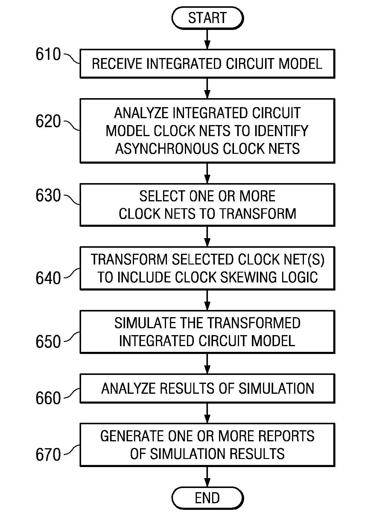
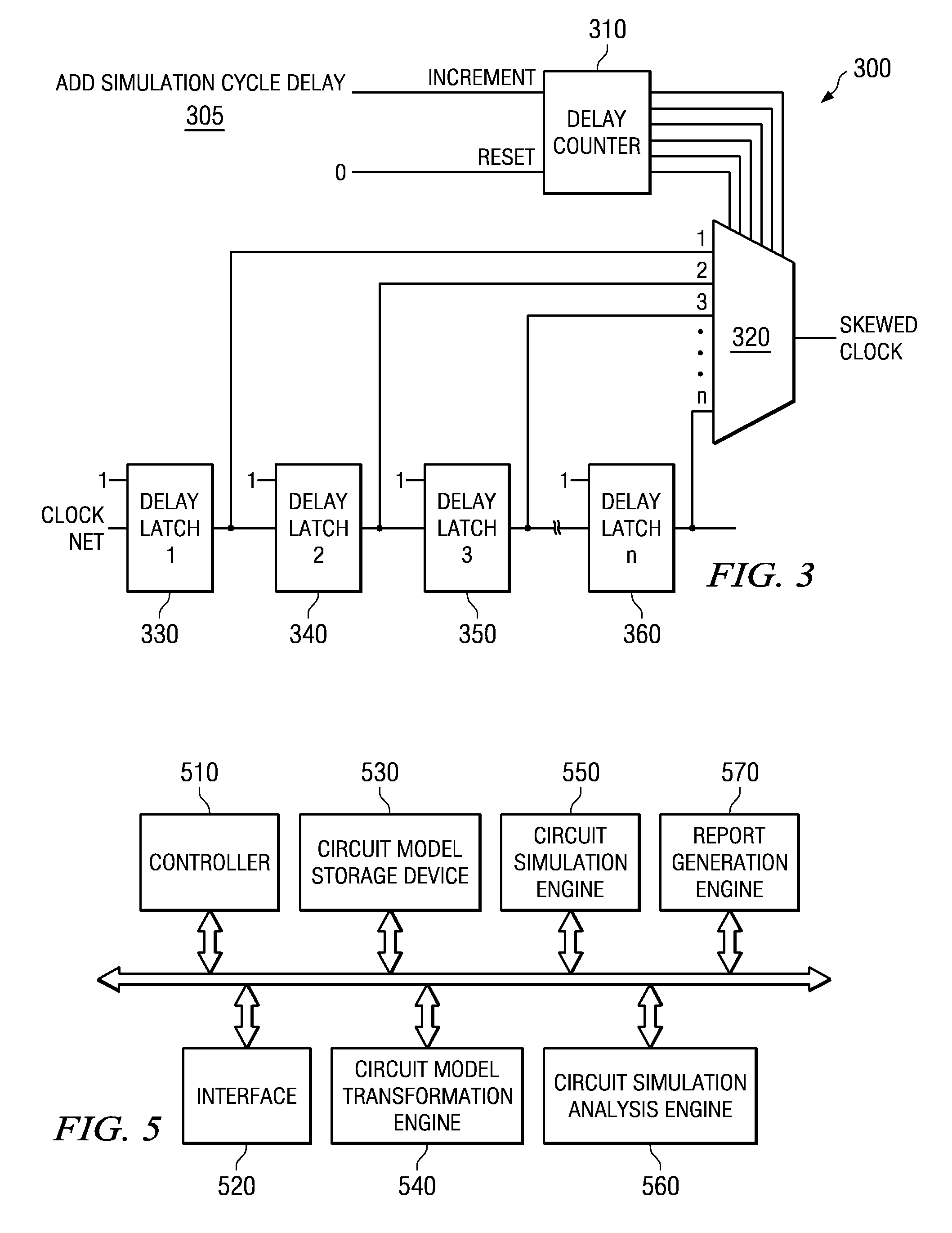
[0039]The illustrative embodiments provide a mechanism for providing clock skewing logic for implementing asynchronous clock modeling from within an integrated circuit design or model. The mechanisms of the illustrative embodiments allow one or more clock nets to be transformed in an integrated circuit design to include clock skewing logic for simulating asynchronous clocks in the integrated circuit design. As a result, a more accurate simulation of the resulting hardware is achieved as opposed to conventional simulation in which clocks are simulated in a manner that makes them appear to be synchronous.

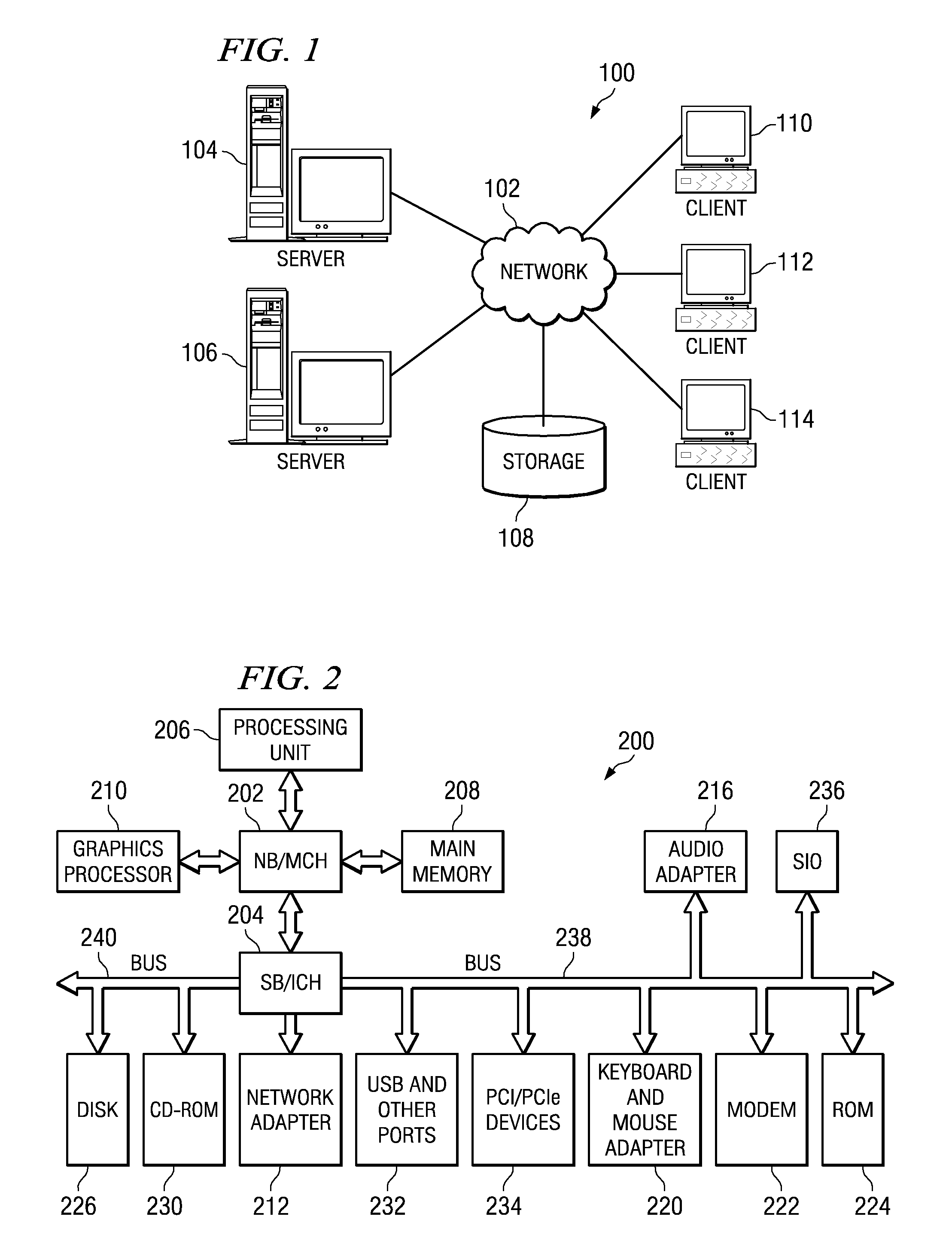
[0040]The illustrative embodiments may be implemented in a single data processing system or may be distributed across a plurality of data processing systems that are coupled to one another via one or more communications networks. For example, a server computing device may provide circuit model simulation and analysis engines that may be applied to integrated circuit designs or models ...


PUM


Abstract

Mechanisms for asynchronous clock modeling in an integrated circuit simulation are provided. The mechanisms of the illustrative embodiments provide clock skewing logic for phase shifting a clock signal in an integrated circuit design. This clock skewing logic adds delay to one or more clocks of an integrated circuit design to thereby place that clock out of phase with other clocks in the integrated circuit design. In one illustrative embodiment, delay is introduced into a clock net in an increasing manner with each enablement of the clock skewing logic. In another illustrative embodiment, the introduced delay is increased and decreased within a window from no phase shift of the clock net up to a maximum phase shift of the clock net. Once the maximum phase shift is reached, the amount of delay introduced is decreased with subsequent enablement of the clock skewing logic.

Description

BACKGROUND[0001]1. Technical Field[0002]The present application relates generally to an improved data processing system and method. More specifically, the present application is directed to a system and method for asynchronous clock modeling in an integrated circuit simulation.[0003]2. Description of Related Art[0004]Electronic design automation (EDA) is now commonly used in the design of integrated circuits. EDA makes extensive use of computers to automate the design process. Once a circuit has been designed and physically laid out, extensive testing is performed to verify that the new design and layout will work as desired. Testing of the new design is typically performed by simulating the design using a computer, which permits relatively fast verification of the circuit without necessitating physically placing the design in silicon.[0005]Static analysis and dynamic simulation are two primary conventional methods employed to analyze and verify circuit behaviors of a design. Dynami...

Claims


Application Information

Patent Timeline
Patent Type & Authority Patents(United States)
IPC IPC(8): G06F17/50G06F9/45
CPCG06F17/5031G06F30/3312
Inventor JA, YEENELSON, BRADLEY S.
Owner INT BUSINESS MASCH CORP
Why Eureka
Try Eureka