
High pressure water blasting device

Inactive Publication Date: 2009-02-03
MASON GEORGE W
View PDF12 Cites 6 Cited by
  • Summary
  • Abstract
  • Description
  • Claims
  • Application Information

AI Technical Summary

Benefits of technology

[0009]This device is designed to improve safety by preventing the hose end from exiting the pipe back towards the user. It is easy to install and fits on any size of pipe. The device is designed to be portable. The device is placed over the opening of the flange of the pipe and partially covers the opening.
[0013]The hose is placed in the opening or through the bushing and the stream of high pressure water is forced into the pipe. When the device is installed the majority of the pipe opening will be covered. A certain portion of pipe opening will not be covered to allow the water to exit the piping, if needed, to prevent damage to the pipe itself and to prevent serious injury to the worker.

Problems solved by technology

If the high pressure hose is allowed to exit the pipe under that amount of pressure serious personal injury or even death may result from the end of the hose striking a worker.

Method used


Image

  • High pressure water blasting device
  • High pressure water blasting device
  • High pressure water blasting device

Examples


Embodiment Construction

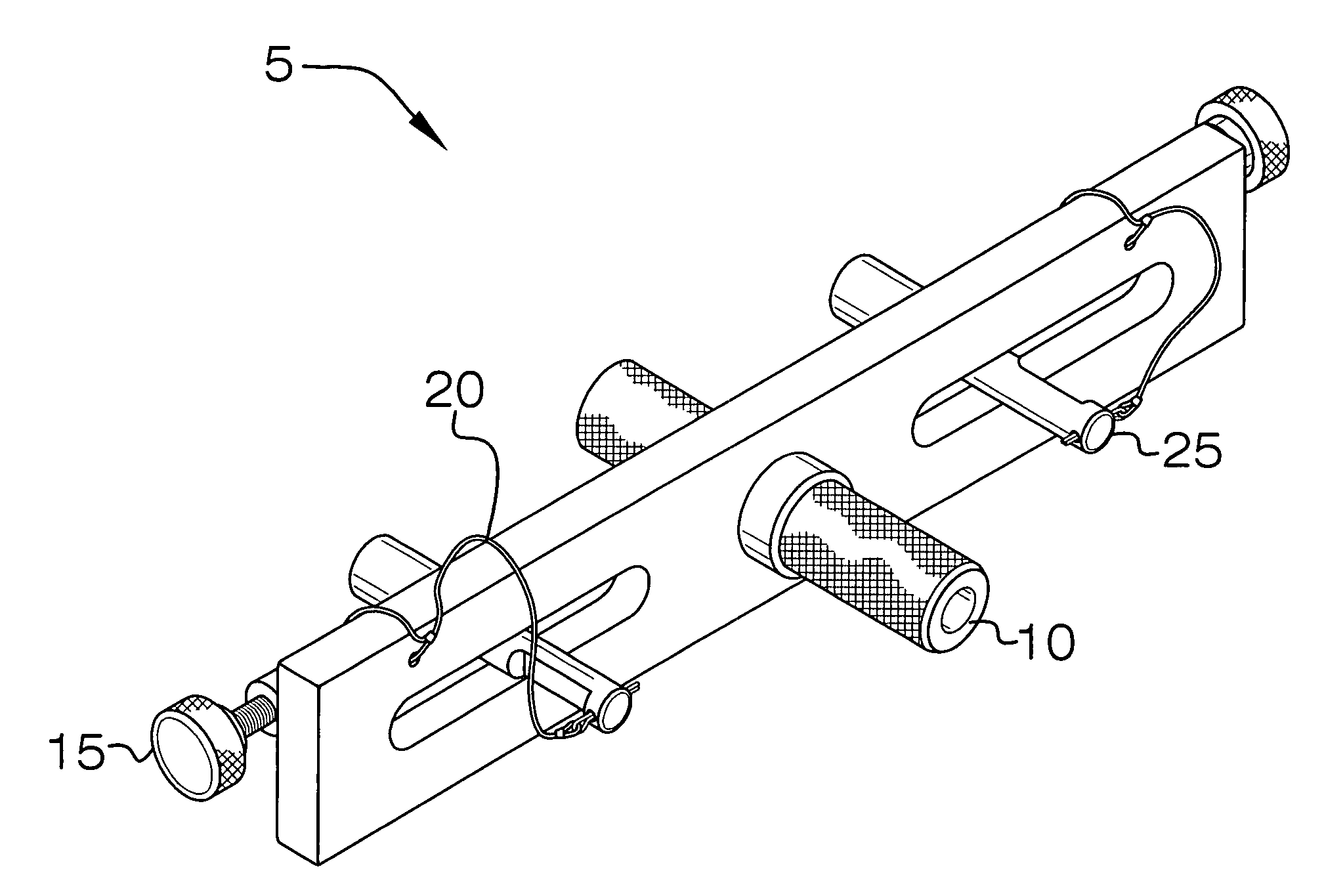
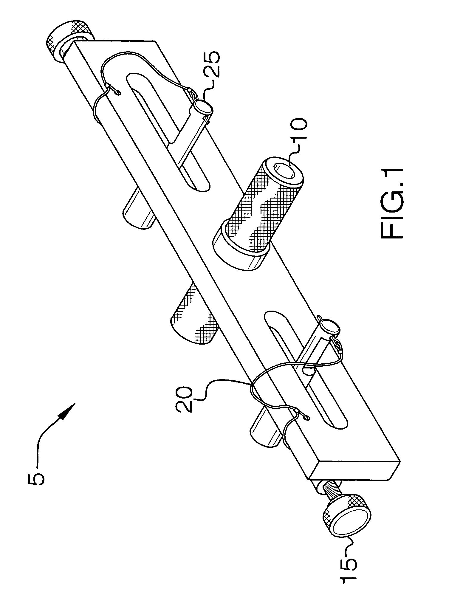
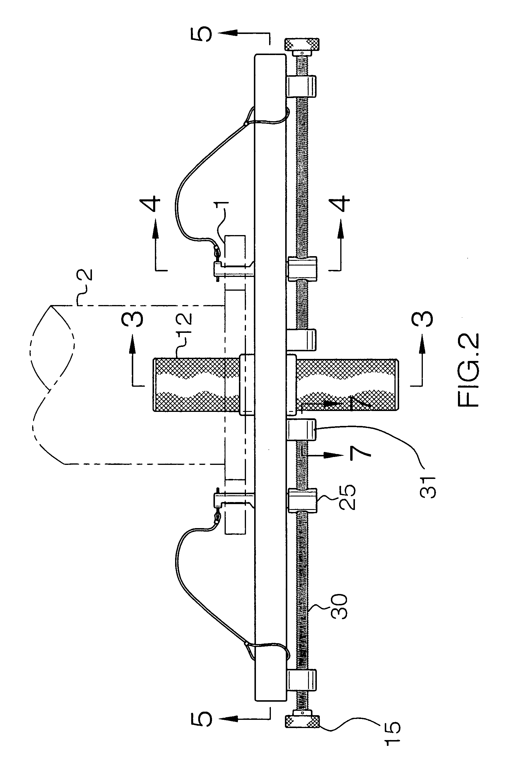
[0021]This device 5 is used to clear industrial pipes. Cleaning a pipe may be difficult and should be done in a safe manner. This device is comprised of a long flat member with an opening in the center of the device and a pair of elliptical openings adjacent to the hole in the center. A high pressure hose is placed through this opening and water under a great deal of pressure is placed in the piping system to clean the pipe.

[0022]The diameter of the opening may be adjusted through the use of a bushing 12. The bushing is hollow through the center and the two sections, 16B and 16T, will be threaded. A hose is threaded through the opening 10 prior to the water being introduced into the piping. In the event that the hose moves backwards in the hole through the pipe opening this device would prevent that because the diameter of the opening would be slightly greater than the opening of the hose.

[0023]This device is installed by separating the union of a section of pipe and installing the ...


PUM

PropertyMeasurementUnit
Pressureaaaaaaaaaa

Abstract

This device will allow a worker to safely, cleanly and most efficiently clean out a pipe or piping system, using high pressure fluid, probably water, that is directed through an opening and into the pipe. This device can be used on any piping system and may be adjusted so that it is secured to any device.

Description

BACKGROUND OF THE INVENTION[0001]A. Field of the Invention[0002]This is a device to clear an obstruction in a pipe, particularly in the chemical or industrial sectors. If chemicals or petroleum products are transported by pipeline, a layer of sediment will form around the inner perimeter of the pipe, which will interfere with the flow in the pipe. This layer of sediment should be periodically cleaned in order to maintain maximum efficiency and to prevent obstruction of the flow in the pipe.[0003]B. Prior Art[0004]There are many other prior art references to methods and devices used to clean pipes and piping systems.[0005]A representative example of this can be found at Semke, U.S. Pat. No. 4,187,563, which is a device for flushing the drainpipe of a sink. However, this device does not particularly relate to sinks and relates more so to flushing a pipe. Another example can be found at Tash, U.S. Pat. No. 4,475,255, which is a pipe-flushing device. However, this is not installed with ...

Claims


Application Information

Patent Timeline
IPC IPC(8): B23P19/04
CPCB08B9/027B08B9/0321E03F9/00Y10T29/53783Y10T29/53778
Inventor MASON, GEORGE W.
Owner MASON GEORGE W
Learn More