Apparatus and method for controlling the radial level of an interface in a centrifugal separator

a centrifugal separator and interface technology, applied in centrifugal force sediment separation, centrifuges, separation processes, etc., can solve the problems of interface layer level displacement to an undesired radial position, difficult to maintain the interface layer level at the desired radial position, etc., to achieve optimal separation results

Active Publication Date: 2009-02-03
ALFA LAVAL CORP AB
View PDF22 Cites 32 Cited by
  • Summary
  • Abstract
  • Description
  • Claims
  • Application Information

AI Technical Summary

Benefits of technology

[0008]By means of such control equipment it is possible to maintain, during substantially the whole operation, the interface layer level at a desired radial position which is optimal for separation results. In particular, it is possible to maintain the interface layer level at the desired position even if the product to be separated has a varying quality. For instance with respect to the quantity of liquid / gas, and a varying temperature which is closed to the boiling point of the liquid. If the pressure in the central gas space of the separation space increases the counter pressure in one of the outlets may increase rapidly, by means of the equipment according to the invention. This rapid increase can occur in such a way that the radial position of the interface layer level is maintained.
[0009]According to an embodiment of the invention, the control equipment is arranged to control the counter pressure in at least one of the first outlet and the second outlet during a flow through said outlet from the centrifuge rotor. According to this embodiment, the invention may be realized in an easy manner by controlling the counter pressure in one of the outlets through an influence of the flow of the heavy phase or the light phase.
[0010]According to a further embodiment of the invention, the control equipment is arranged to also control the counter pressure in at least one of the first outlet and the second outlet by, when needed, permitting the provision of flow into the centrifuge rotor through one of the first outlet and the second outlet. According to this embodiment, the control equipment is thus adapted to permit, when needed, that the flow in one of the outlets flows backwards, i.e. back into the centrifugal rotor. Such an embodiment is especially advantageous in the case that a solid product is discharged via radial nozzles and the percentage of heavy phase in the product to be separated is low, wherein an unallowably high quantity of the heavy phase would leave the centrifuge rotor via these nozzles in such a way that the interface layer level moves too far radially outwardly or disappears completely. Such a process can be prevented by the proposed feeding back of heavy phase or feeding of a control fluid having a density which is substantially the same as the density of the heavy phase.
[0011]According to a further embodiment of the invention, the control equipment comprises at least one valve for controlling the counter pressure in one of the first outlet and the second outlet. Such a valve enables an easy realization of the control of the counter pressure.

Problems solved by technology

As appears from this document, it could be difficult to maintain the interface layer level at the desired radial position during operation of the centrifugal separator.
This can be due to the fact that a non-controllable quantity of separated heavy phase, including separated solid particles, are discharged per time unit.
In such a separation case, it may occur that the interface layer level is displaced to an undesired radial position due to the gas pressure prevailing at the free liquid surface adjacent to the overflow outlet.
Such a displacement of the interface layer level may lead to a poor separation and / or breaking of the water seal.

Method used


Image

  • Apparatus and method for controlling the radial level of an interface in a centrifugal separator
  • Apparatus and method for controlling the radial level of an interface in a centrifugal separator
  • Apparatus and method for controlling the radial level of an interface in a centrifugal separator

Examples


third embodiment

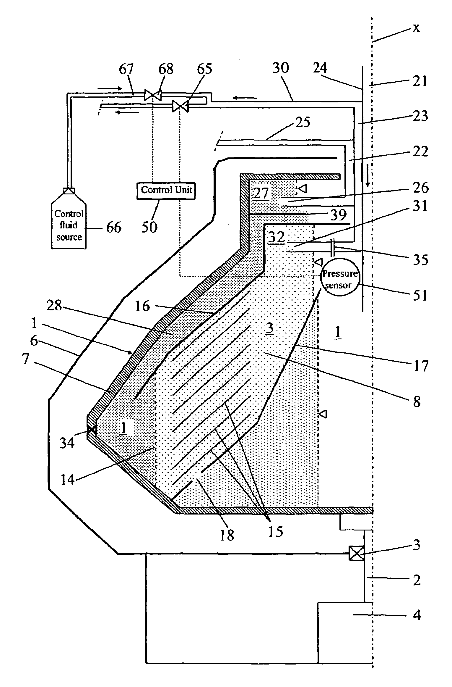
[0037]In the third embodiment, which is disclosed in FIG. 4, an overflow outlet 39 is provided between the radially outer part 11 and the first outlet 22, or more specifically between the radially outer part 11 and the first paring chamber 27.

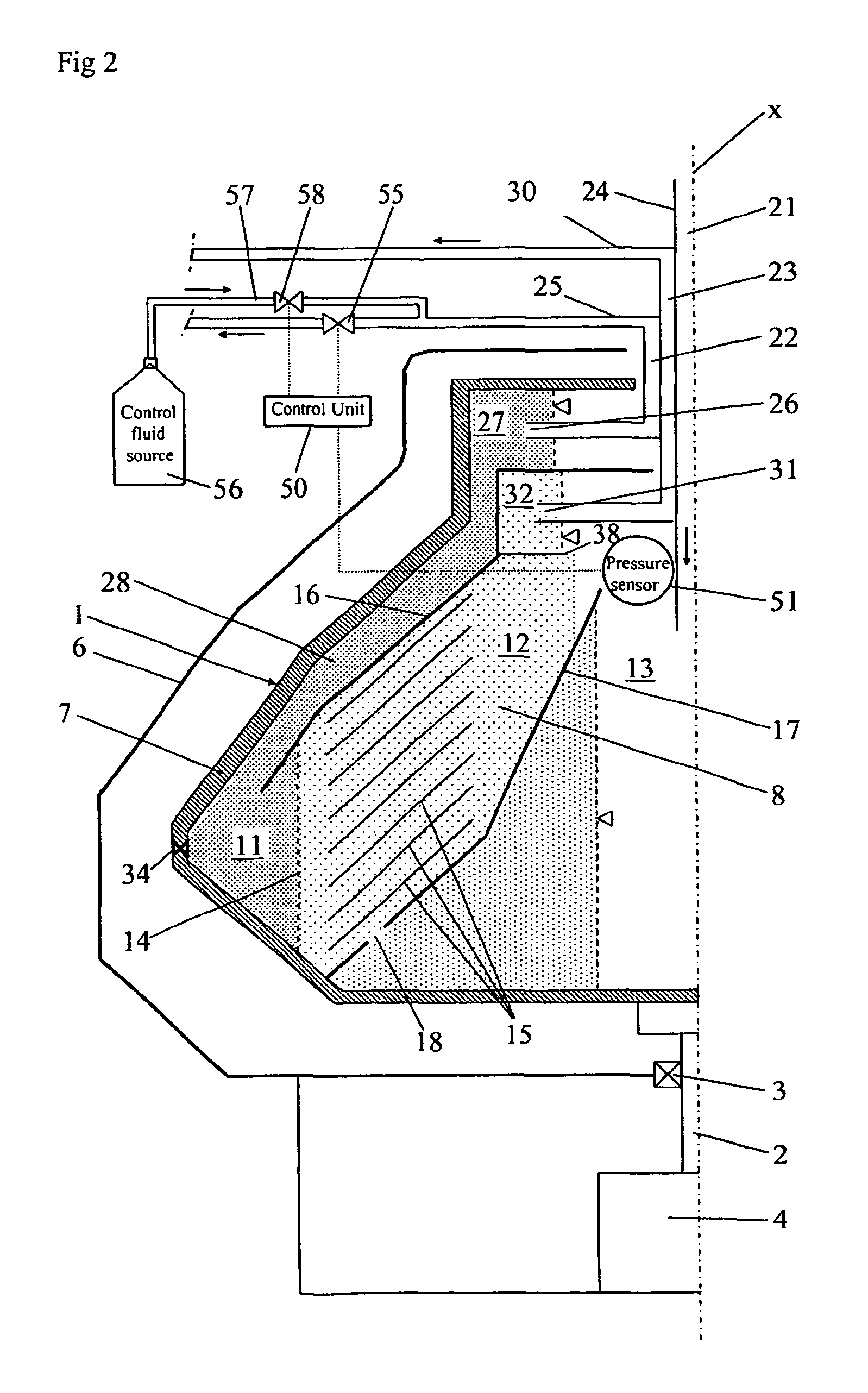
[0038]In the second embodiment, which is disclosed in FIG. 3, and the fourth embodiment, which is disclosed in FIG. 5, the separation space 8 is closed by means of the casing 6, which completely encloses the centrifuge rotor 1 relatively the environment and forms a pressure vessel. In the second embodiment and the fourth embodiment, both the second paring disc 31 and the first paring disc 26 may possibly but not necessarily be provided with a venting hole 35, which permits that the pressure propagates through the two paring chambers 27 and 32.

second embodiment

[0039]In the second embodiment, which is disclosed in FIG. 3, an overflow outlet 38 is provided between the radially inner part 12 and the second outlet 23, or more specifically between the radially inner part 12 and the second paring chamber 32.

fourth embodiment

[0040]In the fourth embodiment, which is disclosed in FIG. 5, an overflow outlet 39 is provided between the radially outer part 11 and the first outlet 22, or more specifically between the radially outer part 11 and the first paring chamber 27.

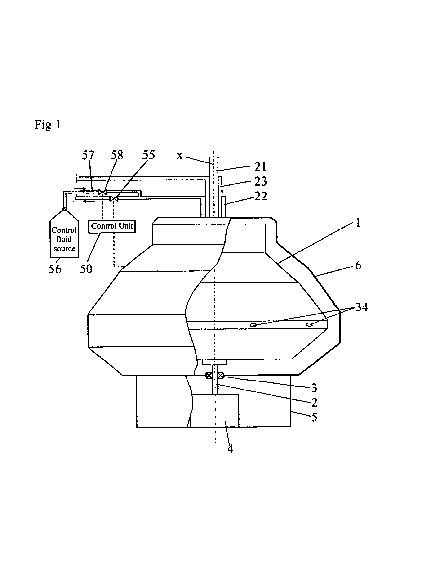
[0041]The centrifugal separator also comprises control equipment arranged to permit during operation control of the interface layer level 14 to a desired radial position by controlling the counter pressure in at least one of the first outlet 22 and the second outlet 23. The control equipment comprises a control unit 50. A sensor is connected to the control unit 50 and provided to sense during operation a parameter related to the gas pressure in the gas-filled space of the separation space 8. In the embodiments disclosed, the sensor is a pressure sensor 51, which senses a gas pressure which is substantially equal to the gas pressure in the central gas-filled space 13 of the separation space 8. In the first and third embodiments, the pressure se...


PUM

PropertyMeasurementUnit
pressureaaaaaaaaaa
counter pressureaaaaaaaaaa
densityaaaaaaaaaa

Abstract

The invention refers to a centrifugal separator and a method of separating a product to a heavy phase and light phase. A centrifuge rotor encloses a closed separation space, which has a radially outer part for the heavy phase, a radially inner part for the light phase and a central gas-filled space. The radially outer part is separated from the radially inner part by a interface layer level. An inlet extends into the separation space for feeding the product. A first outlet extend from the radially outer part for discharge of the heavy phase. A second outlet extends from the radially inner part for discharge of the light phase. A control equipment permits control of the interface layer level to a desired radial position. A sensor senses a parameter related to the gas pressure in the central space. The control equipment controls the counter pressure in the first outlet in response to the sensed parameter for controlling the interface layer level to the desired radial position.

Description

FIELD OF THE INVENTION[0001]The present invention refers to a centrifugal separator for separating a product in at least a relatively heavy phase and a relationship light phase. The invention also refers to a method for separating said product.BACKGROUND OF THE INVENTION[0002]SE-B-514 774 discloses a centrifugal separator of the kind initially defined. As appears from this document, it could be difficult to maintain the interface layer level at the desired radial position during operation of the centrifugal separator. This can be due to the fact that a non-controllable quantity of separated heavy phase, including separated solid particles, are discharged per time unit. If the discharged quantity of heavy phase, for instance would exceed a quantity of fed heavy phase, the interface layer level will be radially displaced outwardly. This problem is solved in SE-B-514 774 by means of a control equipment comprising separate members for supply and discharge of a control fluid which has a ...

Claims


Application Information

Patent Timeline
Patent Type & Authority Patents(United States)
IPC IPC(8): B04B11/00B04B13/00
CPCB04B1/08B04B11/02B04B2013/006
Inventor BORGSTROM, LEONARDHURNASTI, LASSE
Owner ALFA LAVAL CORP AB
Why Eureka
Try Eureka