Bolus tip design for a multi-lumen catheter

a multi-lumen catheter and catheter tip technology, applied in the field of medical devices, can solve the problems of clots around the outside surface of the catheter, trauma to the inside wall of the vein, and the opening may become partially or totally occluded, so as to prevent unnecessary trauma to the patient's vein

Inactive Publication Date: 2009-02-03
BARD ACCESS SYST INC A SUBSIDIARY OF C R BARD
View PDF70 Cites 75 Cited by
  • Summary
  • Abstract
  • Description
  • Claims
  • Application Information

AI Technical Summary

Benefits of technology

[0011]The present invention provides an improved bolus tip design for use in a multi-lumen catheter for the simultaneous injection and withdrawal of fluids to and from a patient. The bolus tip includes an elongate body preferably made of either silicone or polyurethane, having two channels for fluid flow. The edges of the bolus tip are rounded to prevent unnecessary trauma to the patient's vein which can occur when the de...

Problems solved by technology

Problems may result from this design, however.
First, the openings may become partially or totally occluded by the vessel wall or by a build up of blood components.
Second, due to the pressure of fluid exiting the return lumen, a whipping action can occur, wherein the sharp edges of the tip of the catheter lashes back and forth within the vein of a patient, causing trauma to the inside wall of the vein.
This whipping action c...

Method used


Image

  • Bolus tip design for a multi-lumen catheter
  • Bolus tip design for a multi-lumen catheter
  • Bolus tip design for a multi-lumen catheter

Examples


Embodiment Construction

[0027]The present invention satisfies the need for an improved bolus tip design for use with multi-lumen catheters. More particularly, the present invention provides an atraumatic tip design that is efficient and effective in transporting fluids to and from a patient. In the detailed description that follows, it should be appreciated that like reference numerals are used to describe like elements illustrated in one or more of the figures.

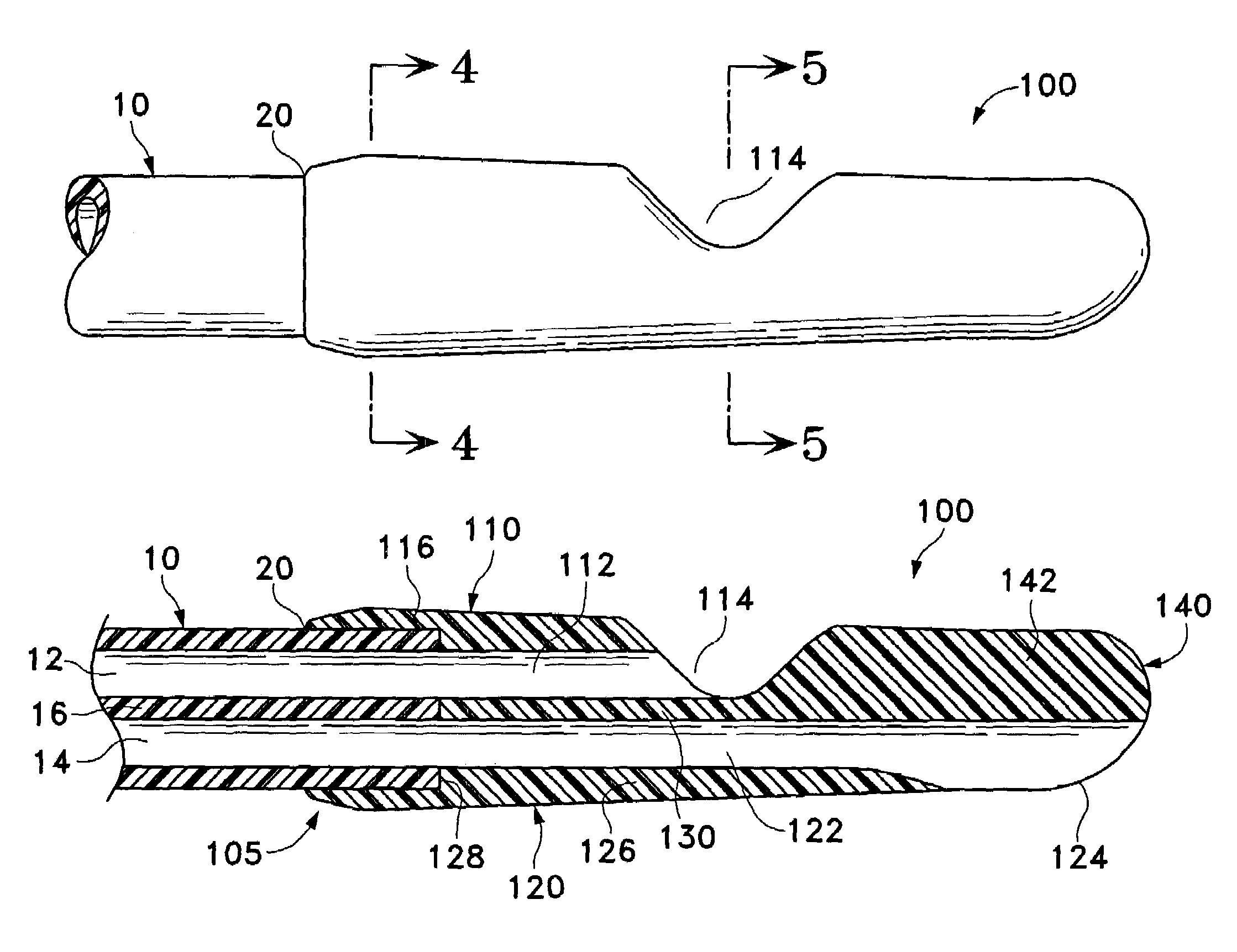
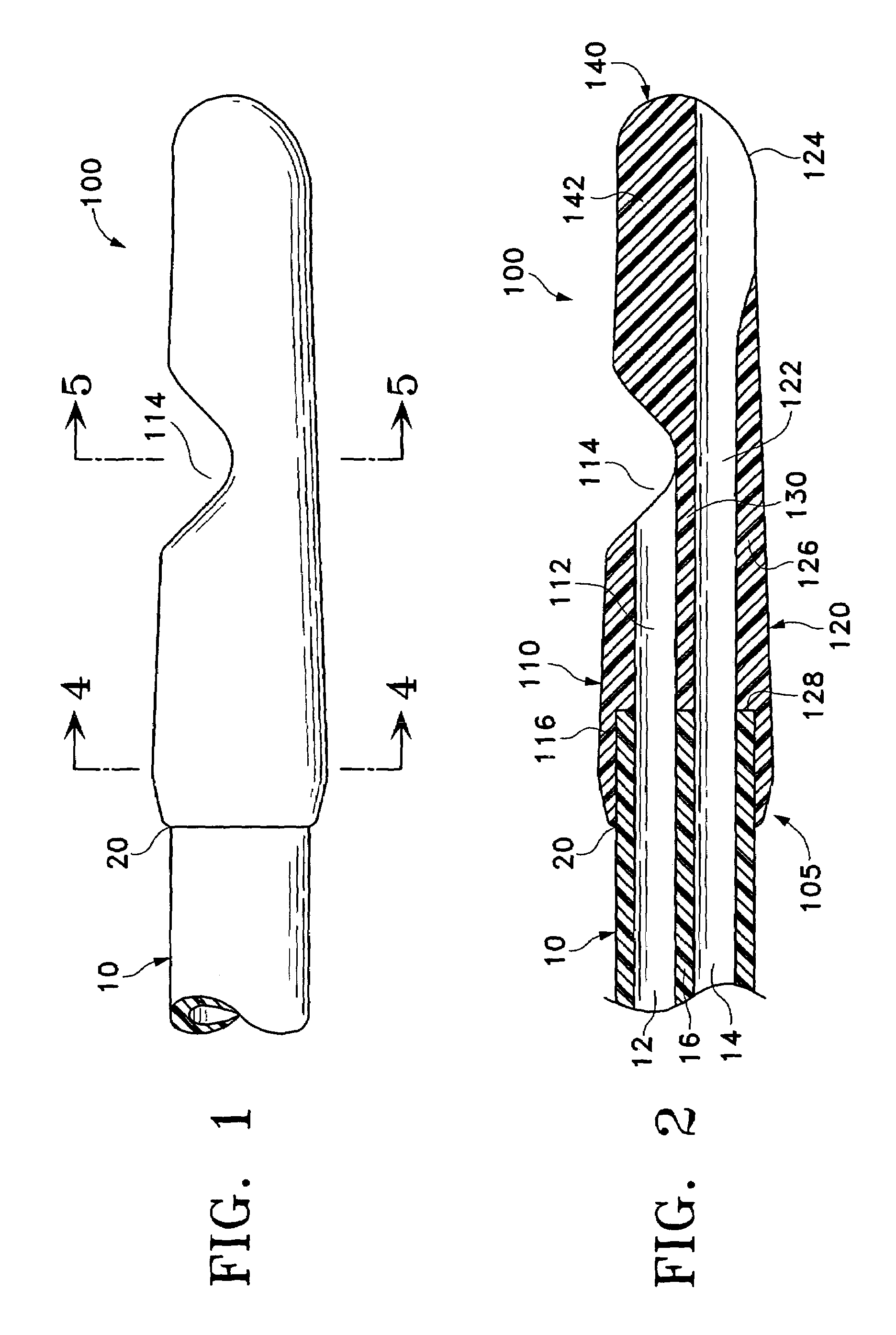
[0028]Turning now to FIG. 1, a first embodiment of the present invention is illustrated. A side view of bolus tip 100 is shown coupled to catheter 10 at point 20. A bolus cavity 114 is located in a side of the bolus tip 100 for the entrance or exit of fluids therefrom. FIG. 2 more elaborately illustrates the inventive concepts of the first embodiment. The bolus tip 100 is oblong and rounded, with a U-shaped portion removed from the bolus tip 100, creating the bolus cavity 114. This U-shaped design is beneficial in that it prevents occlusions by prov...


PUM


Abstract

A bolus tip for a multi-lumen catheter includes a first channel terminating distally in a first opening, and a second channel terminating distally in a second opening. The first opening may be positioned proximal the second opening along a longitudinal axis of the bolus tip and may be positioned on a side of the bolus tip opposite that of the second opening. The first and second openings may extend through an outer wall of the bolus tip to a dividing section. The bolus tip may also include a third channel sized for accommodating a guidewire.

Description

CROSS-REFERENCE TO RELATED APPLICATIONS[0001]This application is a continuation of U.S. patent application Ser. No. 09 / 429,857, filed Oct. 29, 1999, now U.S. Pat. No. 6,786,884, which is incorporated by reference herein.STATEMENT REGARDING FEDERALLY SPONSORED RESEARCH OR DEVELOPMENT[0002]Not applicable.REFERENCE TO A COMPACT DISK APPENDIX[0003]Not applicable.BACKGROUND OF THE INVENTION[0004]The present invention relates generally to medical devices, and more particularly to an improved tip design for a multi-lumen catheter.[0005]Multi-lumen catheters are used for a variety of applications when it is necessary to have two separate fluid pathways. One such application for a multi-lumen catheter is for use in a hemodialysis process. During hemodialysis, a dual-lumen catheter can be employed to simultaneously accommodate opposing blood flow. More specifically, one lumen carries blood from a patient to a dialysis machine where it is processed for the removal of toxins, while the opposing...

Claims


Application Information

Patent Timeline
IPC IPC(8): A61M3/00A61M37/00A61M1/16A61M1/36A61M25/00
CPCA61M1/3653A61M25/0023A61M25/0032A61M25/0068A61M25/0069A61M1/3659A61M1/16A61M25/003A61M25/008A61M2025/0031A61M2025/0034A61M2025/0037A61M2025/0081A61M1/3661
Inventor DIFIORE, ATTILIO E.DECANT, LEONARD J.BELUSKO, VINCENT J.
Owner BARD ACCESS SYST INC A SUBSIDIARY OF C R BARD
Why Eureka
Try Eureka