Eureka AIR delivers breakthrough ideas for toughest innovation challenges, trusted by R&D personnel around the world.

Electrostatic Dust Collector

a dust collector and electrostatic technology, applied in electrostatic separation, solid separation, chemical instruments and processes, etc., can solve the problems of insufficient charge of dust particles, low efficiency of prior art electrostatic dust collectors, and low applied voltage in dust charging section, so as to speed up the effect of accelerating the movement of charged dust particles and reducing the effect of dust collecting area

Inactive Publication Date: 2009-02-03
TOP TECH CO LTD
View PDF12 Cites 12 Cited by
  • Summary
  • Abstract
  • Description
  • Claims
  • Application Information

AI Technical Summary

Benefits of technology

[0011]Because the dust discharging section of the electrostatic dust collector of the present invention employs a plurality of paralleled discharge wires as the discharge electrode and a metal honeycomb net as the counter-electrode, higher voltage can be applied in dust discharging section; as a result, strong corona is formed in dust discharging section between the thin aluminum foil and tungsten wire which results in the emergence of stronger ion flow so as to speed up the movement of charged dust particles to be collected. Electrodes are arranged in rational structure which enables ionized ions to be distributed evenly in the air so that dust particles are more heavily charged and harmful gases are more completely decomposed. Because there are insulating spacers disposed between positive and negative metal electrodes in the dust collecting section, high electric field intensity can be formed between the positive and negative metal electrodes by applying high voltage thereon under the precondition of no air breakdown or disruptive discharge, so that dust particles are more heavily charged. In addition, because the insulating spacers are electric polarized in the strong electric field, the insulating spacers also work as the metal electrodes to collect dust particles, as a result, the dust collecting area is enlarged and dust particles are removed in higher efficiency. The present invention has a simple structure and a low production cost.

Problems solved by technology

However, the efficiencies of prior art electrostatic dust collectors are generally low, particular to tiny dust particles, due to the following reasons: the ionizing voltage applied in dust charging section can not be too high because of the limit by corona current, otherwise the ozone concentration is likely to exceed standards, thus the applied voltage in dust charging section is relatively low, and dust particles are not charged sufficiently; the electric field intensity between metal electrodes is limited in consideration of air breakdown or disruptive discharge, thus Coulomb forces by charged electrodes on tiny dust particles are weak, and dust particles are not easily attracted onto the corresponding electrodes with limited air flow strength.

Method used


Image

  • Electrostatic Dust Collector
  • Electrostatic Dust Collector
  • Electrostatic Dust Collector

Examples


Embodiment Construction

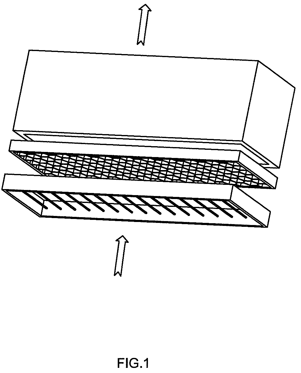
[0018]FIG. 1 shows one embodiment of the present invention applied in an air purifier, wherein said electrostatic dust collector comprises a dust charging section and a dust collecting section. And air flows vertically to said dust charging section and dust collecting section.

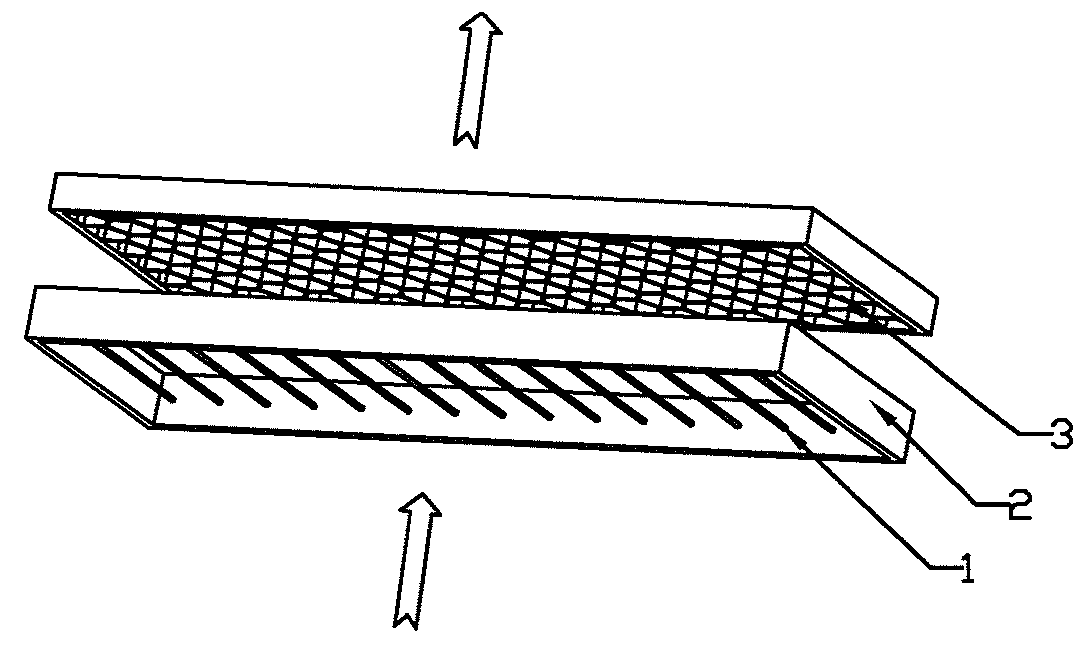
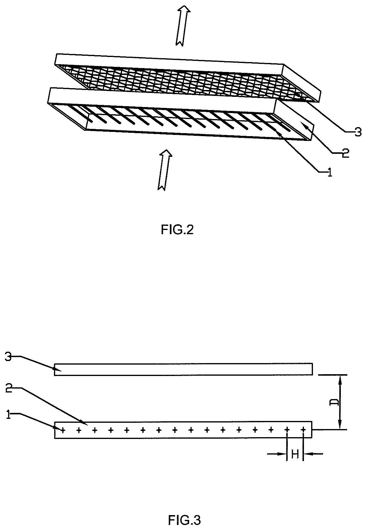
[0019]As shown in FIGS. 2 and 3, said dust charging section comprises: a plurality of tungsten discharge wires 1 which are disposed on an insulating planar frame 2, and a counter-electrode made up of an aluminum honeycomb net 3. Tungsten discharge wires 1 are paralleled disposed at an equal distance, and the plane formed by tungsten discharge wires 1 is parallel to the aluminum honeycomb net 3. The ratio of the distance H between tungsten discharge wires 1 to the discharge passage width D (the distance between the tungsten discharge wires and the aluminum honeycomb net) is in the range of H=(0.8˜1.2) D. The corona voltage applied between the tungsten discharge wires 1 and the aluminum honeycomb net 3 is above o...


PUM

PropertyMeasurementUnit
sizesaaaaaaaaaa
distanceaaaaaaaaaa
corona voltageaaaaaaaaaa

Abstract

An electrostatic dust collector includes a dust charging section and a dust collecting section. The dust charging section includes: a discharge electrode which is made up of a plurality of paralleled discharge wires, and a counter-electrode which is made up of a metal honeycomb net. The dust collecting section includes: positive metal electrodes and negative metal electrodes disposed alternately, and insulating spacers disposed between each of positive metal electrode and negative metal electrode.

Description

CROSS-REFERENCE TO RELATED APPLICATION[0001]The present invention claims priority of CN Patent Application No. 200620064587.3 filed on Sep. 19, 2006, the contents of which are incorporated herein by reference for all purposes.FIELD OF THE INVENTION[0002]The present invention relates to a device for separating particles from air, especially to an electrostatic dust collector which can be applied in an air purifier or an air conditioner, etc.BACKGROUND OF THE INVENTION[0003]The electrostatic dust collector of prior art comprises a dust charging section and a dust collecting section, wherein said dust charging section comprises a plurality of wires applied with high voltage and a counter-electrode which is made up of paralleled wires or plates, and said dust collecting section comprises positive electrodes and negative electrodes disposed alternately. Ionizing air in dust charging section so that dust particles in the air are charged, then the charged dust particles are attracted onto ...

Claims


Application Information

Patent Timeline
Patent Type & Authority Patents(United States)
IPC IPC(8): B03C3/08B03C3/12
CPCB03C3/09B03C3/86B03C3/12B03C3/41B03C3/47B03C2201/04B03C2201/10
Inventor WANG, DONG-LEI
Owner TOP TECH CO LTD
Why Eureka
Eureka Blog
Learn More