Eureka AIR delivers breakthrough ideas for toughest innovation challenges, trusted by R&D personnel around the world.

Fluid monitoring arrangement

Inactive Publication Date: 2009-02-03
ROLLS ROYCE PLC
View PDF12 Cites 13 Cited by
  • Summary
  • Abstract
  • Description
  • Claims
  • Application Information

AI Technical Summary

Problems solved by technology

It is also true that various components within an engine wear and debris from that wearing process become entrained within the fluids.
Nevertheless, analysis generally takes several minutes and so is difficult to utilise with respect to closed loop control of engine function.
In such circumstances if the engine is not properly operated such calculations with regard to costs of operating of the engine are significantly prejudiced.
In short, if incorrect consumable fluids are used the engine will not be operating in accordance with manufacturer's specifications and so the engine will require earlier and probably remedial servicing.
Such servicing costs and remedial action will fall upon the leaser of the engine rather than the operator who clearly has an incentive to use inferior and therefore probably cheaper consumable fluids etc.

Method used


Image

  • Fluid monitoring arrangement
  • Fluid monitoring arrangement

Examples


Embodiment Construction

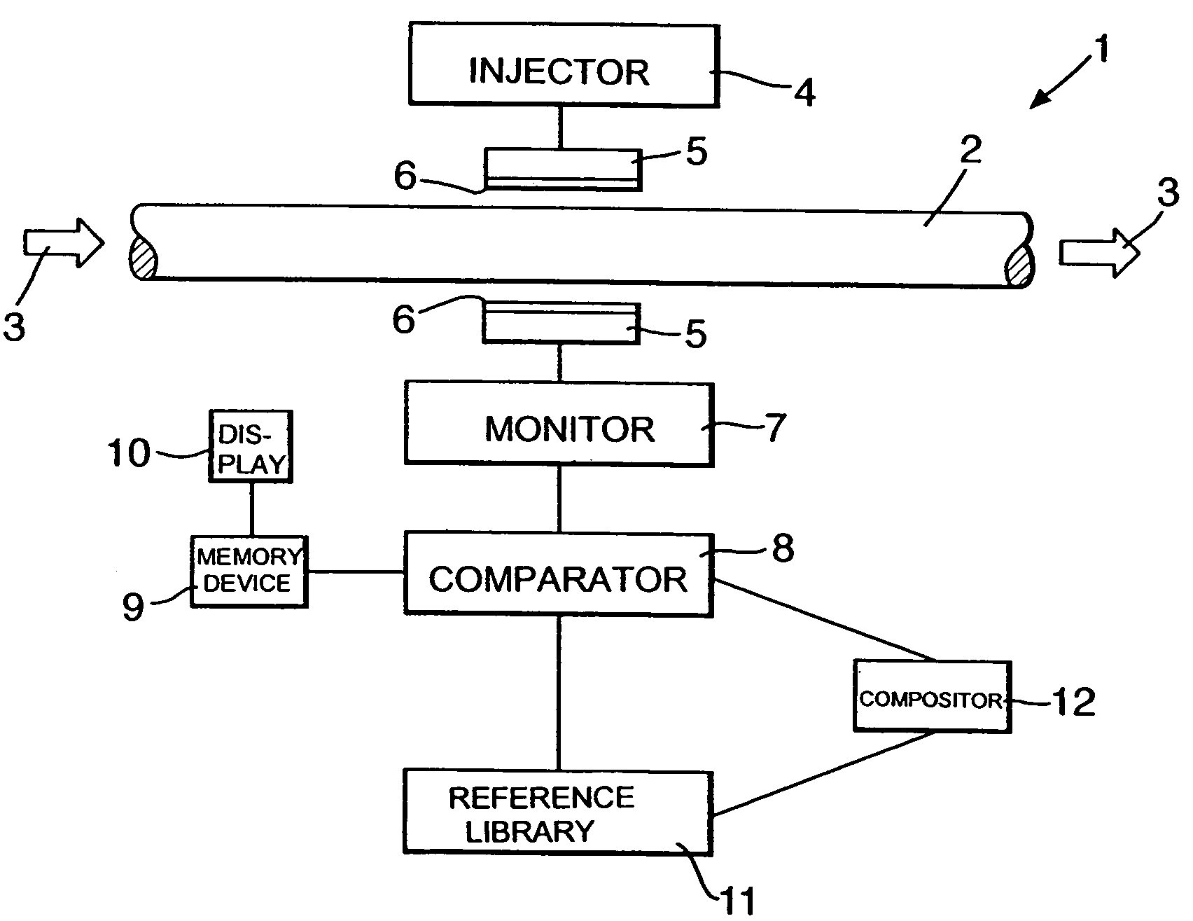
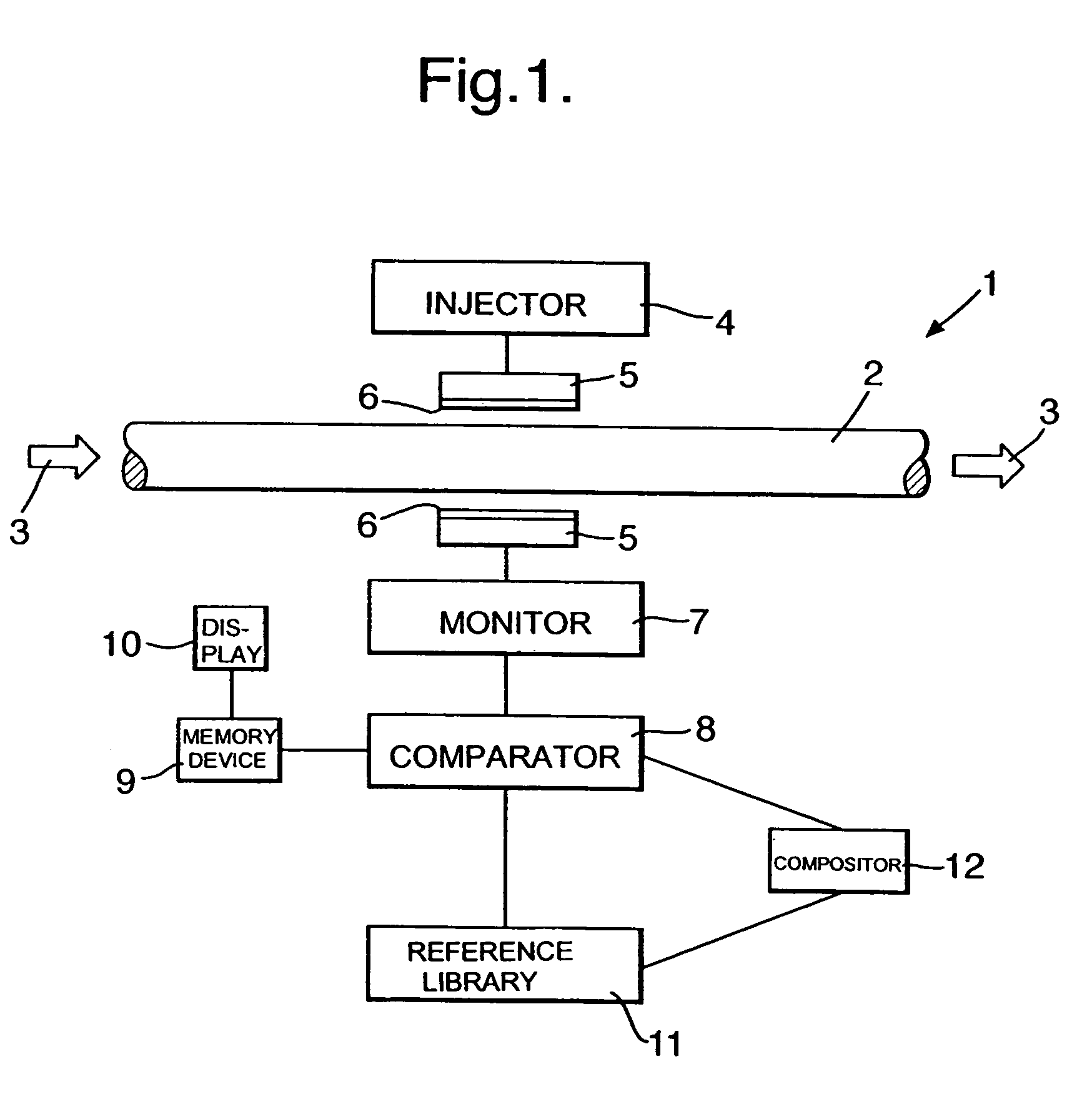
[0025]Referring to the drawing providing a schematic depiction of an engine monitoring arrangement in accordance with the present invention. It is known that engines and in particular turbine engines incorporate a number of conduits through which fluids such as lubricants, coolants and hydraulic oils flow. Thus, conduit 2 contains a fluid flow 3 in the direction of the illustrated arrow heads. Typically, in accordance with the present invention engine monitoring will be performed prior to a conduit filter (not shown) in order to allow monitoring and analysis of the fluid flow 3 constituents and components prior to removal of at least any particulates by such a conduit filter. It would be appreciated that any monitoring after such a filter would be rendered suspect or meaningless due to the removal of such particulates etc.

[0026]In accordance with the present invention a nuclear magnetic resonance (NMR) sensor arrangement 1 is provided. As indicated above, such an arrangement is desc...


PUM


Abstract

A fluid monitoring arrangement 1 for an engine is operated in accordance with a method whereby nuclear magnetic resonance (NMR) interrogation of the fluid flow 3 it is possible to determine whether appropriate fluids and additives are being utilised as well as whether potential detrimental actions occur such as engine wear and carbonisation through particulate components within the flow 3. Generally, an expected signal response from the fluid flow 3 is determined and the actual signal response compared in a comparator 8 with that expected signal response. Divergence in the actual signal response and in particular with regard to its profile is identified and an indication provided in a display 10 with regard to the potential coolant of such divergence. Normally, a reference library 11 is provided of expected signal responses for comparison in the comparator with the actual signal responses. The library 11 stores reference responses for known causes of deviation in the signal response from the NMR interrogation. Thus, by a best fit comparison a prediction as to the cause of divergence as a result of erroneous use of fluids or additives within the fluid flow 3 can be highlighted.

Description

FIELD OF THE INVENTION[0001]The present invention relates to fluid monitoring arrangements and more particularly to such arrangements used with fluid monitoring in engines, with particular regard to service critical turbine engines used for example in aircraft.BACKGROUND OF THE INVENTION[0002]Engines, and in particular turbine engines, include a number of fluids which are consumable in that they deteriorate with time and operational conditions. It is also true that various components within an engine wear and debris from that wearing process become entrained within the fluids. A number of techniques have been devised for elucidating the condition of lubricants, coolants and other consumables within an engine along with determination of particulate debris within fluid flow circulated within an engine. One example of such an approach is using nuclear magnetic resonance (NMR) and one method is outlined in U.K. patent application no. 0022587. In short, NMR signals are presented to the f...

Claims


Application Information

Patent Timeline
IPC IPC(8): G01V3/00G01N24/08
CPCG01N24/08Y02T10/84
Inventor CARE, IAN C DSHEPHERD, TIMOTHY A
Owner ROLLS ROYCE PLC
Why Eureka
Eureka Blog
Learn More