Driving assist apparatus and method for vehicle

a technology of driving assist and vehicle, which is applied in the direction of steering initiation, distance measurement, vessel parts, etc., can solve the problems of increasing cost, increasing computation load, and difficulty in real-time execution of this calculation for existing computing units installed in vehicles, so as to reduce computation load and achieve high accuracy , the effect of easy computation of a path

Active Publication Date: 2009-02-03
TOYOTA JIDOSHA KK
View PDF23 Cites 32 Cited by
  • Summary
  • Abstract
  • Description
  • Claims
  • Application Information

AI Technical Summary

Benefits of technology

[0009]According to the above-described driving assist apparatus and method, the basic path that changes the vehicle orientation from the present direction of the vehicle to the direction of the vehicle at the target position by performing the steering under a predetermined condition is substantially based only on the azimuth angle, so that a path can be determined by relatively simple computation. A target path is computed by adding a straight-line path to the path set as described above. Thus, computing a path is easy, and a path can be computed with high precision.
[0012]According to the above-described driving assist apparatus and method, basic paths (in this case, two basic paths, that is, the first basic path and the second basic path) are set substantially on the basis of only changes in the azimuth angle, and at least one straight-line path is added to a site forward or rearward of the basic paths or between the basic paths, so as to determine a target path. Therefore, even in a case where it is necessary to increase the deflection angle until an intermediate point on the path is reached, and then decrease the deflection angle so that the vehicle direction coincides with the target position vehicle direction as in the case of parallel parking, computation of a path is easy, and a path can be computed with high accuracy.

Problems solved by technology

However, in this related technology, since it is necessary to solve a cubic equation and therefore perform computation of complex numbers, the load of computation becomes great.
Therefore, the real-time execution of this calculation is difficult for the existing computing units installed in vehicles.
Furthermore, the use of a high-performance computing unit leads to a cost increase, and is therefore unfavorable.

Method used


Image

  • Driving assist apparatus and method for vehicle
  • Driving assist apparatus and method for vehicle
  • Driving assist apparatus and method for vehicle

Examples


second embodiment

[0062]Next, the assist operation will be described. In the second control form, assist is performed in a generally-termed parallel parking operation as illustrated in FIG. 7 in which an own vehicle 200 is backed into a parking space 221 between a forward vehicle 201 and a rearward vehicle 202 that are parked along a side end of a road 211. FIGS. 8A and 8B is a flowchart illustrating a second control form. FIG. 9A to 9C are diagrams illustrating the setting of an assist path in this control.

first embodiment

[0063]This embodiment and the foregoing first embodiment are substantially the same in terms of the process up to the determination of a relationship between the reference point and the target position.

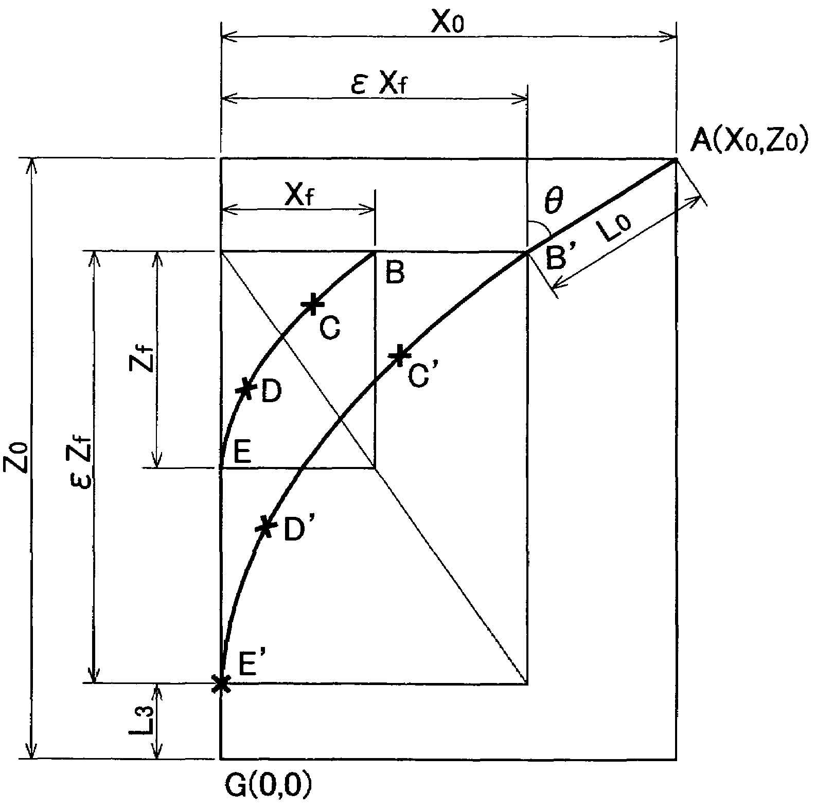
[0064]The path P52 up to a steering switch point M, that is, an intermediate point where the steering angle is reversed, is determined through inverse operation from the target parking position point G (step S31).

[0065]Hereinafter, the position coordinates of the intermediate position point M are expressed as (XM, ZM). It is assumed that the deflection angle θM at the intermediate position point M takes a predetermined set value. Herein, in order to simplify the calculation, the path P52 is assumed to be a path in which the amount of change in the curvature with respect to the running distance from the intermediate point M is changed at −ω, and after the curvature reaches −γmax at a point N, the curvature of −γmax is maintained until the target position G is reached (hereinafter, refe...


PUM


Abstract

A driving assist apparatus for a vehicle that guides the vehicle to a target position is provided. On the basis of the present direction of the vehicle and the direction of the vehicle at the target position, a basic path that changes the vehicle direction so as to coincide with the target direction of the vehicle at the target position is computed. A path from the present position to the target position is computed by adding a straight-line path to the basic path under a predetermined condition.

Description

INCORPORATION BY REFERENCE[0001]The disclosure of Japanese Patent Application No. 2003-183043 filed on Jun. 26, 2003, including the specification, drawings and abstract is incorporated herein by reference in its entirety.BACKGROUND OF THE INVENTION[0002]1. Field of the Invention[0003]The invention relates to vehicular driving assist apparatus and method for determining a locus of run to a target position and assisting the driving of a vehicle so that the vehicle follows the locus of run.[0004]2. Description of the Related Art[0005]A related-art technology for guiding a vehicle to a target position through the use of the automatic steering, the steering command, etc., is disclosed in, for example, Japanese Patent Application Laid-Open Publication No. 5-297935. In this related technology, in order to precisely guide a vehicle to a target position and cause the azimuth angle of the vehicle at the target position to coincide with a target azimuth angle, three basic track patterns are pr...

Claims


Application Information

Patent Timeline
Patent Type & Authority Patents(United States)
IPC IPC(8): B62D6/00B62D6/04B60S9/00G05D1/00B60R21/00B62D15/02G08G1/16
CPCB62D15/0285B60T2201/10
Inventor IWAZAKI, KATSUHIKOSATONAKA, HISASHIKUBOTA, YUICHIENDO, TOMOHIKOMATSUI, AKIRAIWAKIRI, HIDEYUKISUGIYAMA, TORUKAWAKAMI, SEIJIKATAOKA, HIROAKITAKAHASHI, ARATANINOMIYA, YOSHIKI
Owner TOYOTA JIDOSHA KK
Why Eureka
Try Eureka