
Apparatus and methods for monitoring water consumption and filter usage

a technology of apparatus and water consumption, applied in the direction of instruments, machines/engines, filtration treatment, etc., to achieve the effect of accurate and robust method and apparatus, and effectiveness that can deteriorate with wear and tear

Active Publication Date: 2009-02-10
FOOK TIN TECH
View PDF53 Cites 22 Cited by
  • Summary
  • Abstract
  • Description
  • Claims
  • Application Information

AI Technical Summary

Benefits of technology

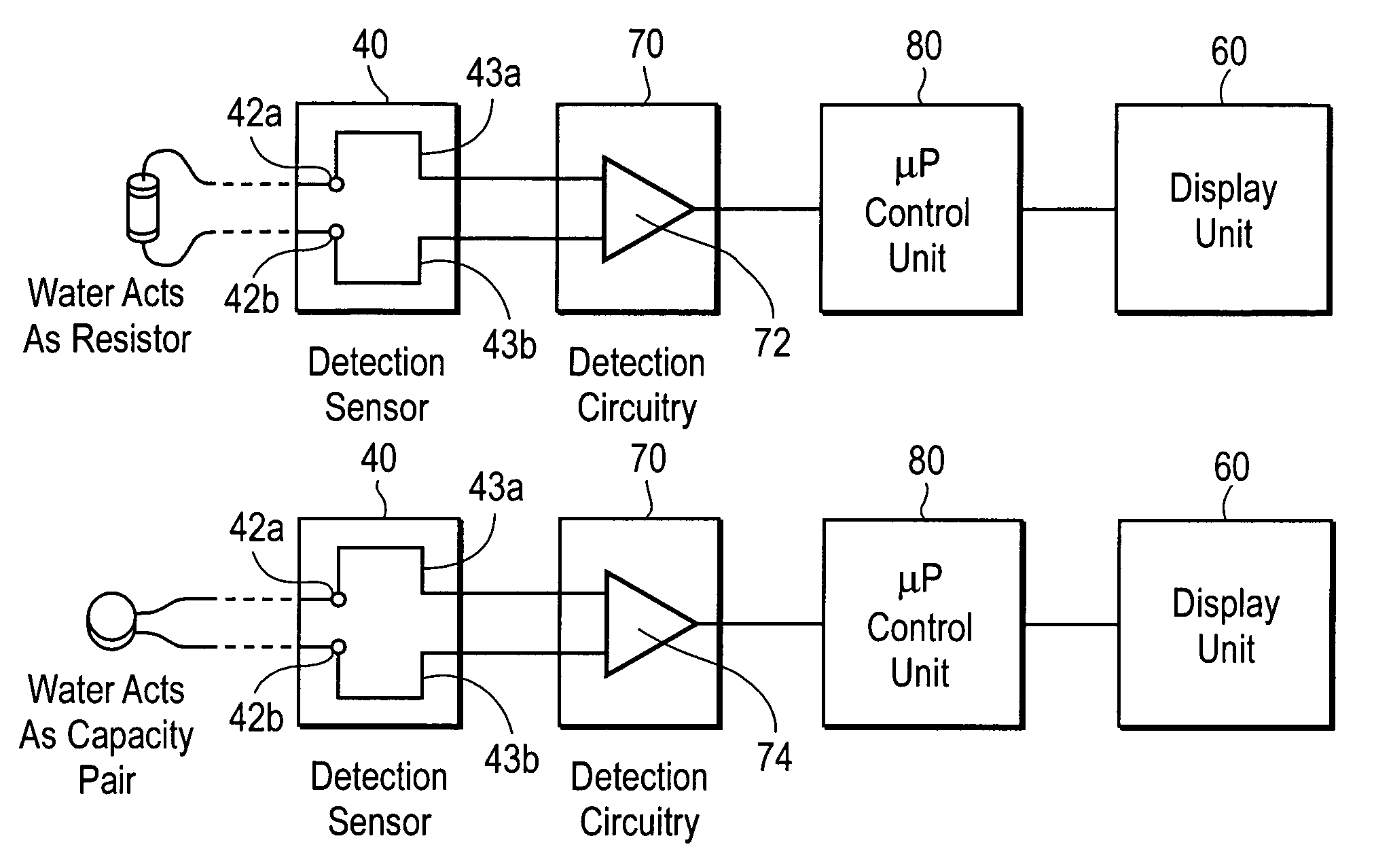
[0010]The present invention determines filter usage by using a microprocessor-controlled sensor to detect and monitor changes in the level of filtered or unfiltered water in a filtered water container. Further, the present invention provides the additional advantages of monitoring filtered water consumption and current water level within the filtered water container.
[0022]The present invention thus provides an accurate and robust method and apparatus for indicating water cartridge usage or exhaustion in a filtered water container. It also omits the use of mechanical devices such as flow meters or those that are connected to the lid for opening / closing or access, whose effectiveness can deteriorate with wear and tear.

Problems solved by technology

Furthermore, the control unit does not use an electronic reading from the detection circuit to determine the water level of the filtered water container when the filtered water container is in the nonfunctional state.

Method used


Image

  • Apparatus and methods for monitoring water consumption and filter usage
  • Apparatus and methods for monitoring water consumption and filter usage
  • Apparatus and methods for monitoring water consumption and filter usage

Examples


Embodiment Construction

Overview of the Filtered Water Container

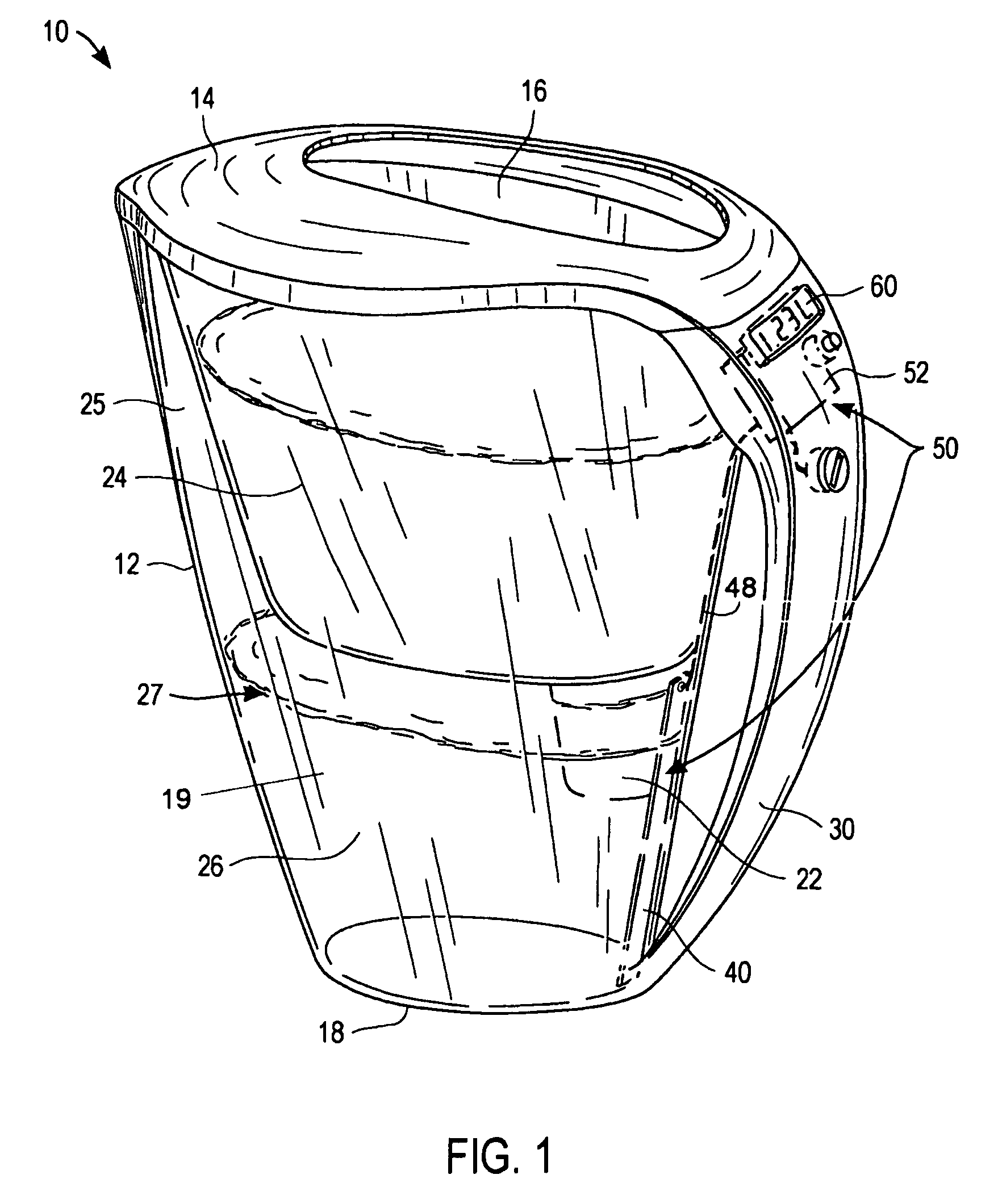
[0044]FIG. 1 depicts a filtered water container 10 according to the present invention for providing filtered drinking water while monitoring water level and determining filter cartridge usage. Container 10 has a main body 12, or vessel, preferably dimensioned as a beverage pitcher, and includes at least three removable parts: a lid 14, a hopper 24 and a water filter cartridge 22. Hopper 24 is configured and dimensioned to fit within and engage with the upper portion of body 12 near lid 14 such that the bottom of hopper 24 and the base 18 of body 12 form a cavity 26 within which filtered water is stored. Filter cartridge 22 is a replaceable filter cartridge and is dimensioned to be removably secured within an opening (not shown) in the bottom of hopper 24, such that a portion of filter cartridge 22 extends into cavity 26. Container 10 also includes a handle 30 attached to or integral with one side of body 12. On an opposite side of body 12, cav...


PUM

PropertyMeasurementUnit
dielectric constantaaaaaaaaaa

Abstract

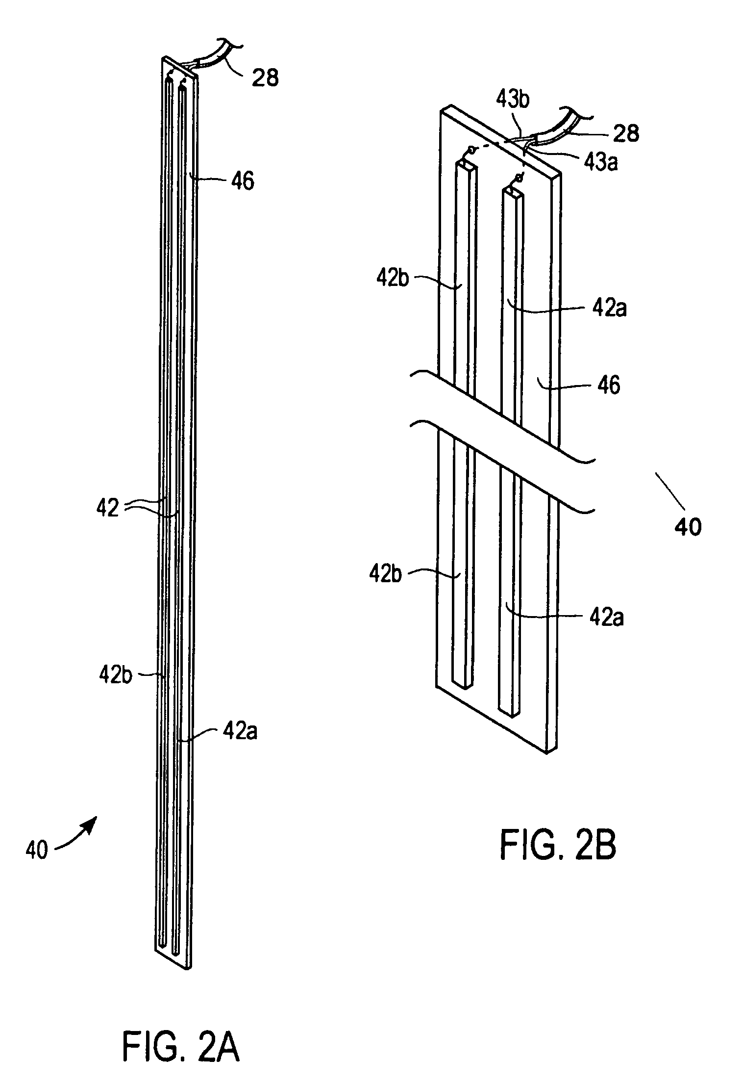
Apparatus and methods for employing electrical properties of water to indicate the level of filtered water in a filtered water container. The container is fitted with a hopper that holds unfiltered water. The hopper is fitted at its base with a removable and replaceable filter cartridge. Water is filtered by draining through the filter medium contained in the filter cartridge into the lower portion of the container. The water level in the filtered water container is monitored by means of one or more water level detector strips in the hopper or in the lower portion of the filtered water container. The detector strips are in electrical communication with a detection circuit and a control unit. The control unit uses the detection strips to monitor water level and uses such data to track filtered water consumption and to determine when the filter cartridge should be replaced.

Description

CROSS REFERENCE TO RELATED APPLICATION[0001]This application is a continuation-in-part of U.S. patent application Ser. No. 10 / 828,484, filed Apr. 19, 2004, now U.S. Pat. No. 7,107,838 which is incorporated by reference herein in its entirety.BACKGROUND OF THE INVENTION[0002]The quality of drinking water varies widely according to the amount of pollutants in the water source. Home water treatment using replaceable filter cartridges fitted in a filtered water container is a popular method to improve drinking water quality. A filter medium is found within the filter cartridge. The filter medium comprises substances and chemical compounds capable of decreasing the concentration of heavy metals such as copper, cadmium, zinc, aluminum, mercury and free chlorine. Some filter media are also capable of limiting the growth of certain microorganisms. It is known that the performance of the filter medium decreases with usage. Thus, a filter cartridge should be replaced after a known amount of w...

Claims


Application Information

Patent Timeline
Patent Type & Authority Patents(United States)
IPC IPC(8): G01F23/24G01F23/26C02F1/00C02F1/28G01F23/00
CPCC02F1/003C02F1/008G01F5/00G01F23/0076G01F23/24G01F23/241G01F23/243C02F2209/42C02F2303/14C02F2307/04C02F2209/445G01F23/804
Inventor CHAI, JOHN Y.CHAI, SUNNY N.KO, DEREK C.
Owner FOOK TIN TECH
Learn More