Fuel filler cap

a technology of fuel filler and outer cap, which is applied in the direction of caps, sealing, liquid handling, etc., can solve the problems of increasing the number of members, increasing the size of the fuel filler cap, and reducing the number of parts, so as to reduce the number of parts and facilitate re-constructing. , the effect of easy manufacturing

Inactive Publication Date: 2009-02-10
ASTEER
View PDF10 Cites 15 Cited by
  • Summary
  • Abstract
  • Description
  • Claims
  • Application Information

AI Technical Summary

Benefits of technology

[0021]The fuel filler cap of the present invention has advantageous effects of that, firstly, the outer cap be applied the external force can be released from the inner cap of fitting in the filler port in order to secure the gastightness by the inner cap under any directions of the external force applied to the outer cap. Secondly, in addition, the outer cap is not accompanied by a partial breakage so that the fuel filler cap of the invention can reuse the outer cap or the pressing plate released.
[0022]The aforementioned individual advantageous effects come from the construction, in which the wedge-shaped projections of the outer cap are fitted in the annular grooves formed by the supporting plate and the pressing plate. In case the outer cap receives the downward external force, the wedge-shaped projections slip down along the annular slants of the annular grooves so that the plate engagement means is released to release the inner cap from the outer cap. In case the outer cap receives the transverse or upward external force, on the other hand, the wedge-shaped projections push up the pressing plate with the releasing load or greater thereby to release the plate engagement means thereby to release the inner cap from the outer cap. In either case, accordingly, the fuel filler cap of the present invention can be easily reconstructed by fitting the wedge-shaped projections again in the annular grooves, because of the simple construction for releasing the fitting between the annular groove and the wedge-shaped projections.
[0023]The plate engagement means provides a first advantageous effect to release the outer cap from the inner cap, in case the outer cap receives the transverse or upward direction while the supporting plate and the pressing plate are integrally turned in the opening / closing direction of the fuel filler cap. The plate engagement means composed of the engaging projections and the engaging holes respectively assigned to the supporting plate and the pressing plate can be easily manufactured and also can adjust the adequate releasing load by setting the structure or number of the engaging projections and the engaging holes. Thus, the plate engagement means composed of the engaging projections and the engaging holes has an advantageous effect to set the amount of the external force releasing the outer cap from the inner cap by utilizing the engaging relations between the engaging projections and the engaging holes against the downward or transverse external force forcing the inner cap open.
[0024]Thus, the supporting plate provides a base for releasing the outer cap from the inner cap. In addition, the supporting plate is positioned just above the seal ring so that it can be utilized as the portion to crush the seal ring. This structure contributes to the reduction of the number of parts. Moreover, this supporting plate appears that the supporting plate radially extends with respect to the seal ring. In other words, the supporting plate also acts to protect the seal ring against contacting with the wedge-shaped projections that slip down in case the outer cap receives the downward external force. Further, to form the annular pendulous portion of the supporting plate surrounding the seal ring has the advantageous effect to protect the seal ring more reliably against contacting with the wedge-shaped projections.

Problems solved by technology

This makes it impossible to mount the released outer cap again on the inner cap.
As a result, problems arise to increase the number of members and / or to make a size of the fuel filler cap larger.

Method used


Image

  • Fuel filler cap
  • Fuel filler cap
  • Fuel filler cap

Examples


Embodiment Construction

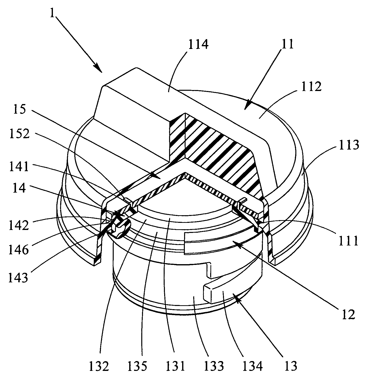
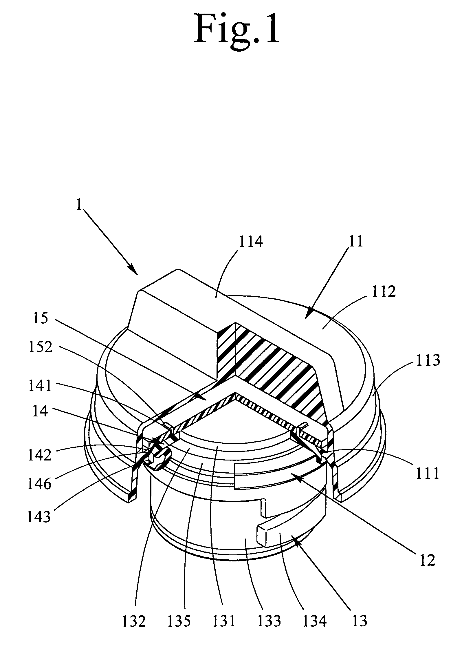
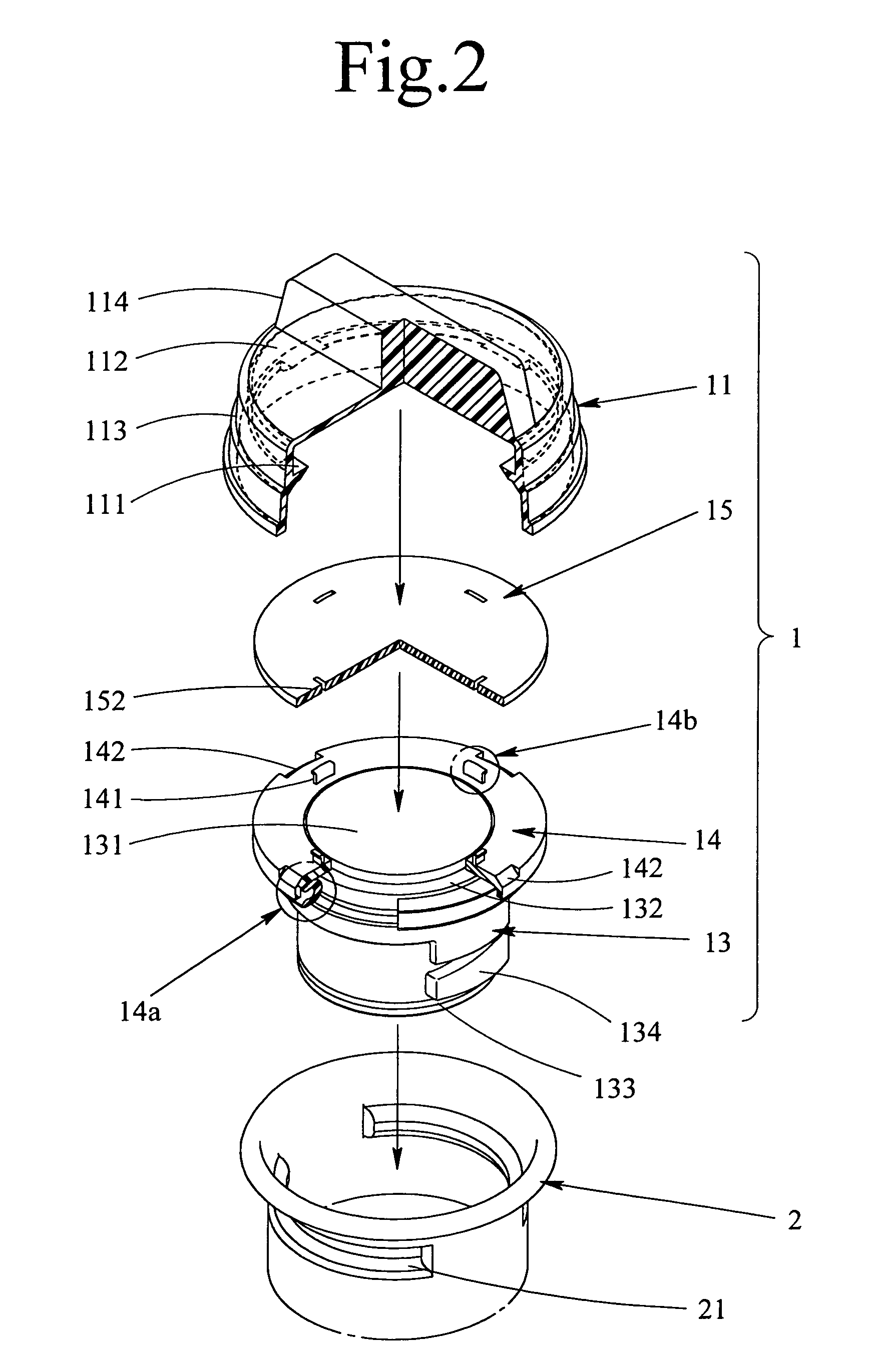
[0040]Embodiments of the invention will be described with reference to the accompanying drawings. The invention is suitable for a bayonet-type fuel filler cap 1 requiring no torque restricting function. Thus, this bayonet-type fuel filler cap 1 is shown in the individual drawings.

[0041]The embodiment is directed to the bayonet-type fuel filler cap 1 for realizing the sealing properties by pushing and crushing a seal ring 12 to the upper edge of a filler port 2, as shown in FIG. 1 to FIG. 5. Specifically, the fuel filler cap 1 is basically composed of: an inner cap 13 made of a resin into a substantially cylindrical member and fitted on the outer face of the seal ring 12; and an outer cap 11 made of a resin into a cover member and fitted on the inner cap 13. Moreover, the entire fuel filler cap of this embodiment is further constructed by laying a pressing plate 15 made of a resin into a circular outer shape in a top plan view, on a supporting plate 14 mounted on the inner cap 13.

[00...


PUM


Abstract

This invention provides a fuel filler cap that can release an outer cap from an inner cap without influences of direction of the external force when it applied. The fuel filler cap 1 comprises the outer cap 11 constructed by an upper face portion 112, a skirt portion 113 extending from the outer circumference of the upper face portion 112 and a plurality of wedge-shaped projection 111 formed on the inner face of the skirt portion 113, the pressing plate 15, and the inner cap 13 constructed by a supporting plate 14 having annular slants 142 formed downward by chamfering the peripheral edge of its upper face intermittently, a seal ring 12 and a plurality of annular groove 146 defined by the individual annular slants 142 of the supporting plate 14 and by the lower face of the pressing plate 15 laid over the supporting plate 14.

Description

BACKGROUND OF THE INVENTION[0001]1. Field of the Invention[0002]The present invention relates to a fuel filler cap for closing the filler port of an automobile.[0003]2. Description of the Related Art[0004]The fuel filler cap is desired to exhibit a stable gastightness when it is closed. Particularly, the fuel filler cap is required not to release its closed state accidentally even where either a direct external force or an external force resulting from a deformation of a car body applied. In the prior art, therefore, there has been proposed the fuel filler caps, which includes an inner cap to be fitted in the filler port and an outer cap to cover the filler port and to thereby perform a turning operation of the fuel filler cap. In these fuel filler caps including the inner cap and the outer cap, it is adopted construction to secure gastightness in that the outer cap is released from the inner cap while leaving the inner cap in its closed state in the filler port where the external f...

Claims


Application Information

Patent Timeline
Patent Type & Authority Patents(United States)
IPC IPC(8): B65D53/00B60K15/05B60K15/04B65D39/10B65D41/04B65D51/00
CPCB60K15/0406Y10S220/33
Inventor YOSHIDA, HIROMITSUONO, TAKAMI
Owner ASTEER
Why Eureka
Try Eureka