Station for wireless network

a wireless network and wireless network technology, applied in wireless commuication services, digital output to print units, multiplex communication, etc., can solve the problems of troublesome setting of ess-id in a device without sufficient input interfaces, troublesome separate cable connection, low connection stability, etc., and achieve the effect of relatively easy re-construction of wireless lans

Inactive Publication Date: 2007-11-01
138 EAST LCD ADVANCEMENTS LTD
View PDF3 Cites 12 Cited by
  • Summary
  • Abstract
  • Description
  • Claims
  • Application Information

AI Technical Summary

Benefits of technology

[0019] The station of the present invention can realize the function as the relay device to establish a wireless network. The invention ensures establishment of a temporary wireless network including the station of the invention without changing the settings in an access point in an existing wireless LAN. The station receives the terminal identification via the temporary wireless network and is thus connectable with the existing wireless LAN. The arrangement of the invention thus ensures easy connection of the station with the existing wireless LAN.
[0022] This arrangement facilitates setting and resetting in the case of connecting a device without sufficient input interface for settings to a wireless LAN.
[0030] This arrangement enables the terminal identification to be readily acquired via the communication utilizing the initial relay identification, even after storage of the relay identification into the relay storage module. The wireless LAN can be reconstructed relatively easily with the initial relay identification, even when the setting of the relay identification in the station is completely unknown.

Problems solved by technology

The drawback of the Ad Hoc system is relatively low connection stableness.
Setting of the ESS-ID is rather troublesome in a device without sufficient input interfaces, such as a printer.
This prior art technique, however, requires a troublesome, separate cable connection only for settings in the wireless LAN.
The problems discussed above are not limited to the settings of the printer, but are commonly found in the settings in the case of connecting any device without sufficient input interfaces for settings to the wireless LAN.

Method used


Image

  • Station for wireless network
  • Station for wireless network
  • Station for wireless network

Examples


first embodiment

A. First Embodiment

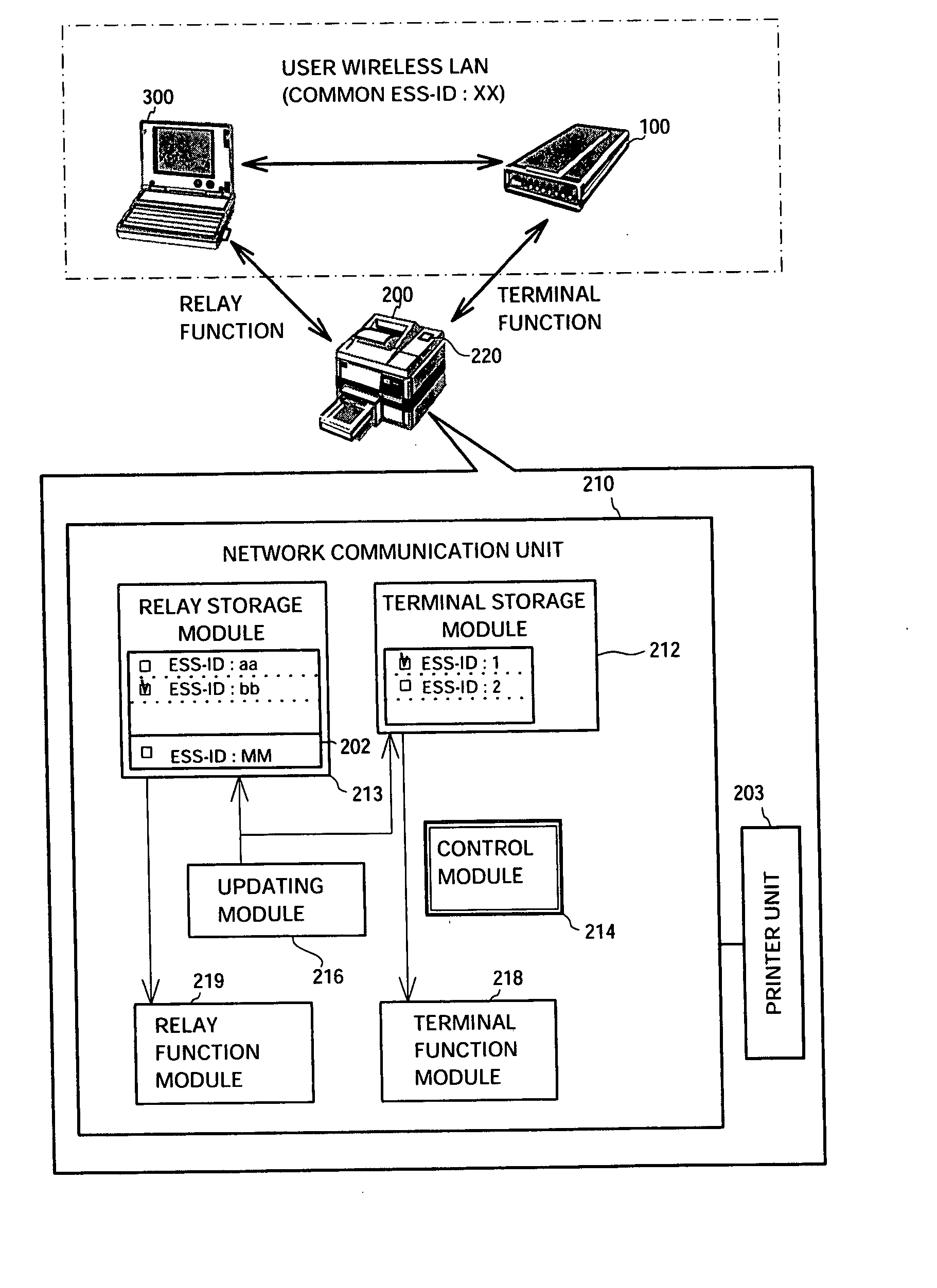
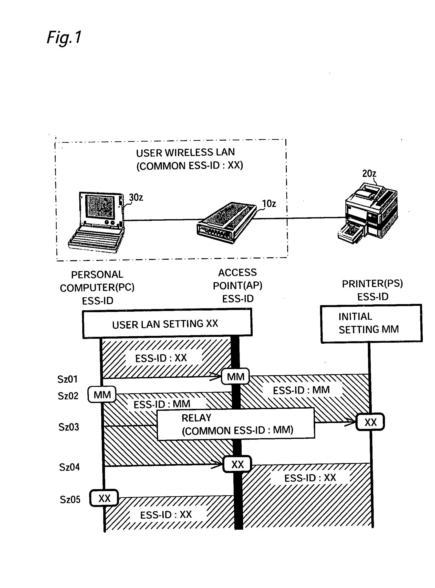
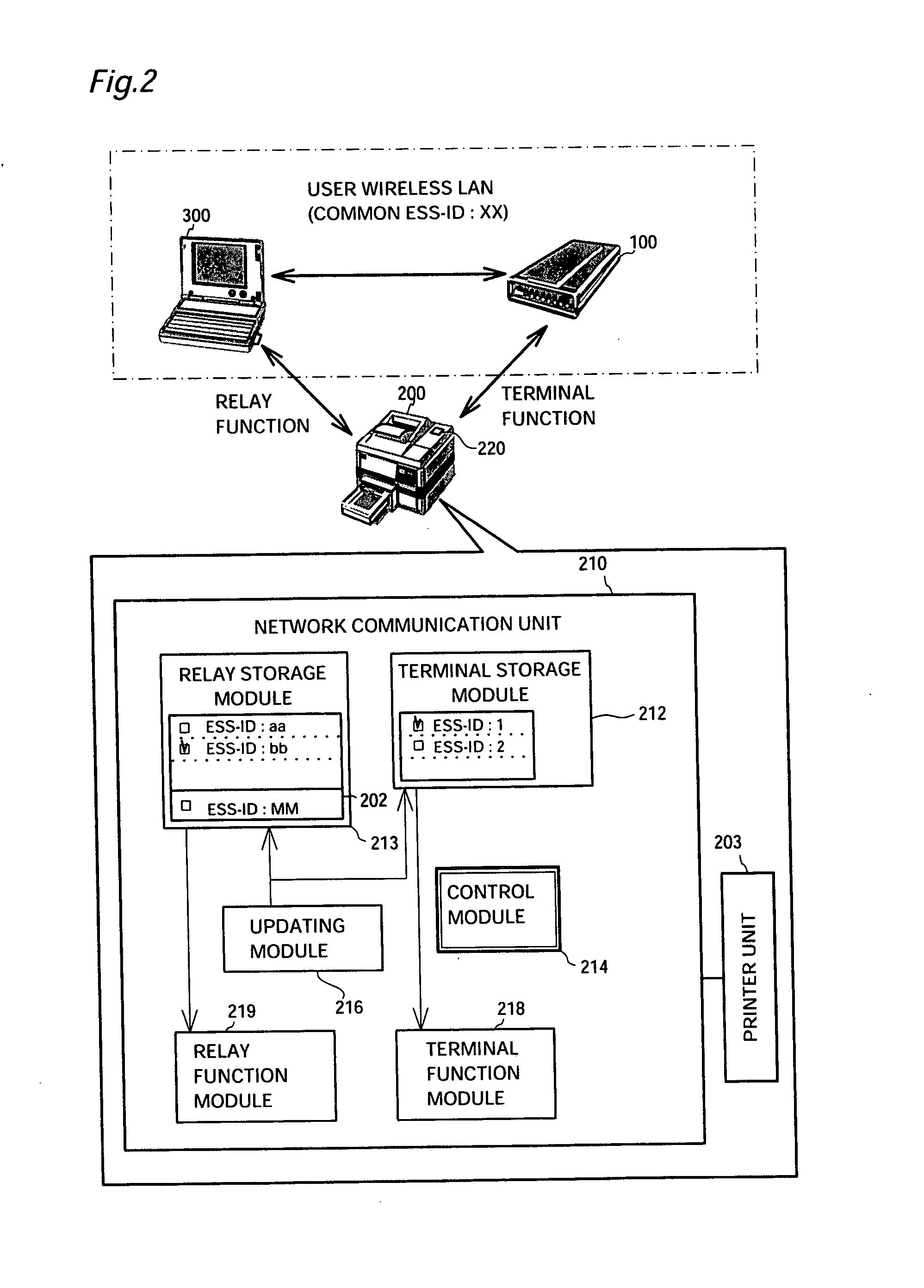
[0044]FIG. 2 illustrates the construction of a printer 200. The user wireless LAN is constructed to include an access point 100 and a personal computer 300. The personal computer 300 is one of the stations currently involved in the user wireless LAN and sets a common ESS-ID ‘XX’ for the user wireless LAN in the printer 200, based on a user's input. The printer 200 and the personal computer 300 have radio communication modules to attain wireless communication with the access point 100.

[0045] A functional block diagram of the printer 200 is also shown in FIG. 2. The printer 200 has a microcomputer including a CPU and memories. The respective functional blocks illustrated in FIG. 2 are attained by software executed by the CPU in this embodiment, although these functional blocks may be actualized by hardware.

[0046] The printer 200 has a printer unit 203 and a network communication unit 210. The printer unit 203 is the functional block to carry out printing functions...

second embodiment

C. Second Embodiment

[0073] The following describes a second embodiment of the present invention, where the control module 214 realizes the switchover control function, by which the terminal function module 218 is temporarily ceased and the relay function module 219 is activated at a preset timing even after the acquisition of the ESS-ID. In the second embodiment discussed here, the ESS-ID of the printer 200 is supposed to be transferred to an additional printer PS2 (500). This series of processing is carried out in response to a click of the AP function extension checkbox 263 included in the ESS-ID input window 260.

[0074]FIG. 6 schematically illustrates the process of transferring the ESS-ID in the second embodiment, with a timing chart 800 of processing. The printer 200 has acquired in advance the common ESS-ID for the user wireless LAN as discussed previously in the first embodiment. The printer 200 may continue the wireless communication as the access point even after the acquis...


PUM


Abstract

A wireless network device, such as a printer, to enter an infrastructure-type user wireless LAN as a station, has an additional access point function. A printer having an ESS-ID ‘MM’ as an initial setting is connected with a user wireless LAN, which includes an access point and a personal computer and uses a common ESS-ID ‘XX’. In this case, the procedure changes the ESS-ID set in the personal computer to ‘MM’ to establish an infrastructure-type communication with the printer. This arrangement enables the ESS-ID set in the printer to be changed to the common ESS-ID ‘XX’ for the user wireless LAN without varying the ESS-ID set in the access point. The technique of the invention ensures easy connection of any device without sufficient input interfaces to the wireless LAN.

Description

[0001] This is a continuation of application Ser. No. 10 / 284,482 filed Oct. 31, 2002. The entire disclosures of the prior application, application Ser. No. 10 / 284,482 is hereby incorporated by reference.BACKGROUND OF THE INVENTION [0002] 1. Field of the Invention [0003] The present invention relates to a station to be connected to a wireless network. [0004] 2. Description of the Related Art [0005] With recent advancement of network technology, devices like computers and printers are mutually connected via a network. The typical techniques that have come into practical use include the Internet and LANs (Local Area Networks). Wireless networks have become popular, in addition to cable networks. [0006] There are two major systems to attain a wireless network; one is called the infrastructure system and another is called the Ad Hoc system. The infrastructure system utilizes a star-shaped network where stations (ST) are concentrically connected by a relay center called an access point (A...

Claims


Application Information

Patent Timeline
Patent Type & Authority Applications(United States)
IPC IPC(8): H04Q7/24H04B7/24G06F3/12H04L12/28H04W8/26H04W16/26H04W28/04H04W76/02H04W84/12H04W88/04H04W88/08
CPCH04W8/26H04W28/04H04W88/08H04W84/12H04W88/04H04W76/02H04W76/10
Inventor GASSHO, KAZUHITOSHIOHARA, SUSUMU
Owner 138 EAST LCD ADVANCEMENTS LTD
Why Eureka
Try Eureka