

Current-input current-output reconfigurable passive reconstruction filter
a passive reconstruction and current input technology, applied in the field of reconstruction filtering, can solve the problems of large power consumption, cost savings, area, etc., and achieve the effect of high linearity, highly programmable, and easily reconfigurable reconstruction filtering
- Summary
- Abstract
- Description
- Claims
- Application Information
AI Technical Summary
Benefits of technology
Problems solved by technology
Method used
Image

Examples
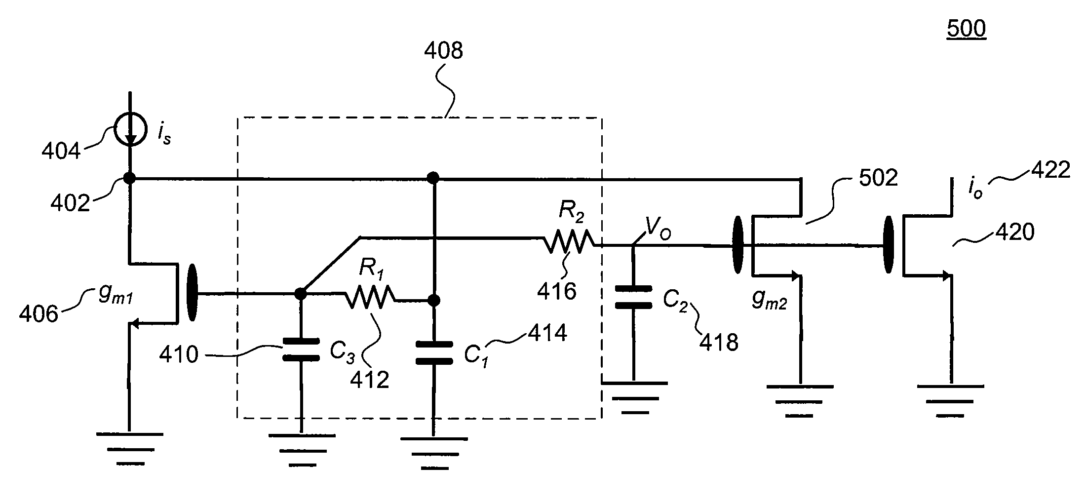
example implementation 500
[0051]Example implementation 500 is structurally similar to example implementation 400, but also includes an output transistor 502, as shown in FIG. 5. Output transistor 502 has a drain terminal coupled to input node 402, a source terminal coupled to ground, and a gate terminal coupled to the gate terminal of input transistor 420 of the mixer.
[0052]The transfer function of the reconstruction filter of FIG. 5 can be written as:
[0053]H(s)=VOis=1 R1R2C1C2C3s3+(R2C2C3+R1C1C2+R1C1C3+R2C1C2)s2+(C1+C2+C3+gm1R2C2)s+gm1+gm2
where VO represents the voltage at the input of the mixer, as shown in FIG. 5.
[0054]In an embodiment, input transistor 406 and output transistor 502 are matched according to a transconductance ratio, which allows example implementation 500 to have a smaller area compared to example implementation 400. Further, example implementation 500 may be suited for cases in which input current signal iS 404 has a small AC signal swing (e.g., less than 25%)....
example implementation 600
[0056]Example implementation 600 is structurally similar to example implementation 400, but also includes a diode-connected transistor 602 having a first terminal and a second terminal coupled to input node 402 and a third terminal coupled to ground. The transfer function of the reconstruction filter of FIG. 6 can be written as:
[0057]H(s)=VOis=1 R1R2C1C2C3s3+(R2C2C3+R1C1C2+R1C1C3+R2C1C2+gm2R1R2C2C3)s2+(C1+C2+C3+gm1R2C2+gm2(R1C3+R2C2+R1C2))s+gm1+gm2
where VO represents the voltage at the input of the mixer, as shown in FIG. 6.
[0058]FIG. 7 illustrates another example implementation 700 of a reconstruction filter according to an embodiment of the present invention. Similar to FIG. 4, FIG. 7 shows a reconstruction filter according to an embodiment of the present invention coupled to the input stage of a subsequent circuit. In an embodiment, the subsequent circuit includes a mixer, as shown above in FIG. 3.
example implementation 700
[0059]Example implementation 700 is structurally similar to example implementation 400, but also includes an operational amplifier 702 coupled between input transistor 406 and RC network 408. As such, the first and third terminals of input transistor 406 are coupled to one another and also to the inverting input of operational amplifier 702. The non-inverting input of operation amplifier 702 is coupled to the second end of first resistor R1 412, forming a feedback loop in the reconstruction filter. The output terminal of operational amplifier 702 is coupled to the first end of first resistor R1 412.
[0060]The transfer function of the reconstruction filter of FIG. 7 can be written as:
[0061]H(s)=iOiS=gmR1R2C1C2C3s3+(R2C2C3+R1C3C2+R1C1C3+R2C1C2)s2+(C1+C2+C3+gm1R2C2)s+gm.
[0062]As would be understood by a person skilled in the art based on the teachings herein, example implementations 500, 600, and 700 have similar functionality, operation, and performance as desc...
PUM
 Abstract
Description
Claims
Application Information