Lubricating system for metal-demolition shears

a technology of lubricating system and metal shear, which is applied in the field of heavy-duty machinery, can solve the problems of reducing productivity and wearing each other down, and achieve the effect of prolonging the service li

Active Publication Date: 2009-02-10
STANLEY WORKS THE
View PDF16 Cites 12 Cited by
  • Summary
  • Abstract
  • Description
  • Claims
  • Application Information

AI Technical Summary

Benefits of technology

[0007]One or more embodiments of the present invention provides a lubricating system for a metal demolition shears that lubricates one or more of the various wear surfaces. A lubricating system according to the invention may be configured to do so automatically with each cycle of the upper jaw opening and closing. Additionally, where multiple wear surfaces are lubricated, a lubricating system according to the invention may be configured such that the various wear surfaces are lubricated in sequential order. A lubricating system according to the invention thus keeps the various wear parts properly lubricated, thereby extending their service life, while eliminating the need for the operator to stop operations in order to lubricate the wear parts.
[0015]According to a further aspect of one or more embodiments of the present invention, the method further includes detaching a second upper jaw from the lower jaw prior to pivotally connecting the first upper jaw to a lower jaw. Accordingly, the method can be used to quickly and efficiently retrofit a lubricated upper jaw onto a conventional non-lubricated shears.

Problems solved by technology

As they do so, they can wear each other down.
That, however, necessitates stopping operation of the shears, which reduces productivity.

Method used


Image

  • Lubricating system for metal-demolition shears
  • Lubricating system for metal-demolition shears
  • Lubricating system for metal-demolition shears

Examples


Embodiment Construction

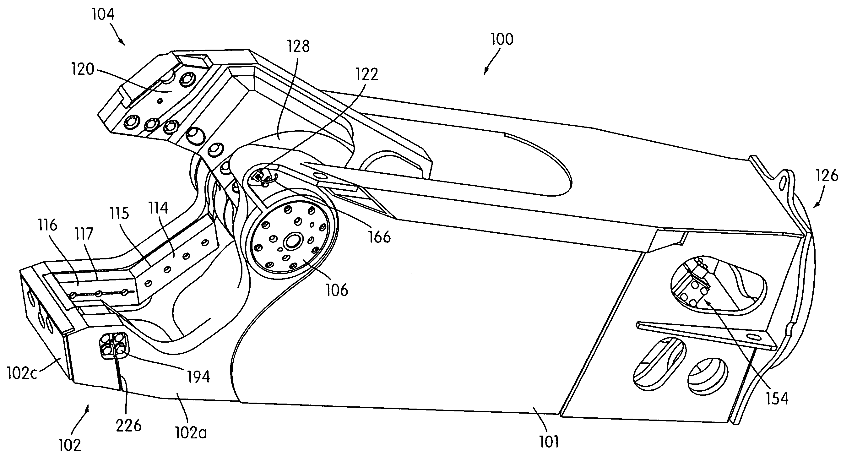
[0039]A metal demolition shears 100 that incorporates an embodiment of a lubricating system according to the invention is illustrated generally in FIGS. 3-6. The shears 100 has lower jaws 102 and upper jaws 104 that is pivotally connected to the lower jaws 102 by means of pivot structure 106. The lower jaw 102 includes left-hand lower jaw plate 102a, right-hand lower jaw plate 102b, and cross-member 102c interconnecting the two. The upper jaw 104 is driven to pivot open and closed relative to the lower jaw 102 by means of a hydraulic cylinder 108 (illustrated schematically in FIG. 10).

[0040]Upper primary and secondary blade insert members 110, 112, respectively, are secured to a blade seat portion of the upper jaw 104 and provide primary and secondary upper cutting edges 111, 113, respectively. Similarly, lower primary and secondary blade insert members 114, 116, respectively, are secured to seating surfaces formed along the right-hand lower jaw side plate 102b and provide primary a...


PUM

PropertyMeasurementUnit
heightaaaaaaaaaa
areaaaaaaaaaaa
cutting forcesaaaaaaaaaa

Abstract

A lubricating system for a heavy-duty metal demolition shears provides lubricant to one of more wear surfaces on one or more wear portions in the shears. The system includes a hydraulic lubricant pump that is actuated by the main hydraulic control system by means of which the jaws of the shears are opened and closed, and may include a sequential valve to distribute lubricant to various wear portions in sequential fashion. The lubricating system may lubricate one or more wear surfaces of the lateral blade stabilizers, primary and secondary blade(s) on the upper and / or lower jaws, pivotal connections between jaws and / or between the upper jaw and the hydraulic cylinder, and a forward wear plate. The lubricating system may be retrofitted onto a conventional non-lubricated shears by replacing a conventional upper jaw with a lubricated upper jaw and lubricating system.

Description

CROSS-REFERENCE[0001]This application is a continuation-in-part of application Ser. No. 10 / 886,052, now U.S. Pat. No. 7,240,869, entitled “LUBRICATING SYSTEM FOR METAL-DEMOLITION SHEARS,” filed Jul. 8, 2004, the contents of which are incorporated herein by reference in their entirety.FIELD OF THE INVENTION[0002]The invention relates to heavy-duty machinery having wear parts with wear surfaces that need to be lubricated. More particularly, the invention relates to heavy-duty metal demolition shears and demolition attachments such as multi-jaw processors used in concrete and steel processing and demolition.BACKGROUND OF THE INVENTION[0003]As illustrated in FIGS. 1 and 2, in general, a heavy-duty metal demolition shears 10 of the sort in which a lubricating system according to the invention may be incorporated has a stationary lower jaw 12 and an upper jaw 14 that pivots about a pivot structure 16 to open and close. A hydraulic cylinder 18 drives the upper jaw 14 to open and close the ...

Claims


Application Information

Patent Timeline
Patent Type & Authority Patents(United States)
IPC IPC(8): B22C19/00
CPCB23D31/008B23D33/00E02F3/965E04G23/082
Inventor SEDERBERG, CLAYTON P.SWANSON, MICHAEL W.
Owner STANLEY WORKS THE
Why Eureka
Try Eureka