Imaging catheter and methods of use for ultrasound-guided ablation

Inactive Publication Date: 2009-02-10
BOSTON SCI SCIMED INC
View PDF53 Cites 42 Cited by
  • Summary
  • Abstract
  • Description
  • Claims
  • Application Information

AI Technical Summary

Benefits of technology

[0006]The present invention provides ultrasound imaging catheters, systems and methods for their use. Catheters and systems of the present invention will be particularly useful to monitor the positio

Problems solved by technology

Such probes are poorly tolerated by patients unless they are fully anesthetized.
Further, these probes can be rather large (i.e., 2

Method used


Image

  • Imaging catheter and methods of use for ultrasound-guided ablation
  • Imaging catheter and methods of use for ultrasound-guided ablation
  • Imaging catheter and methods of use for ultrasound-guided ablation

Examples


Embodiment Construction

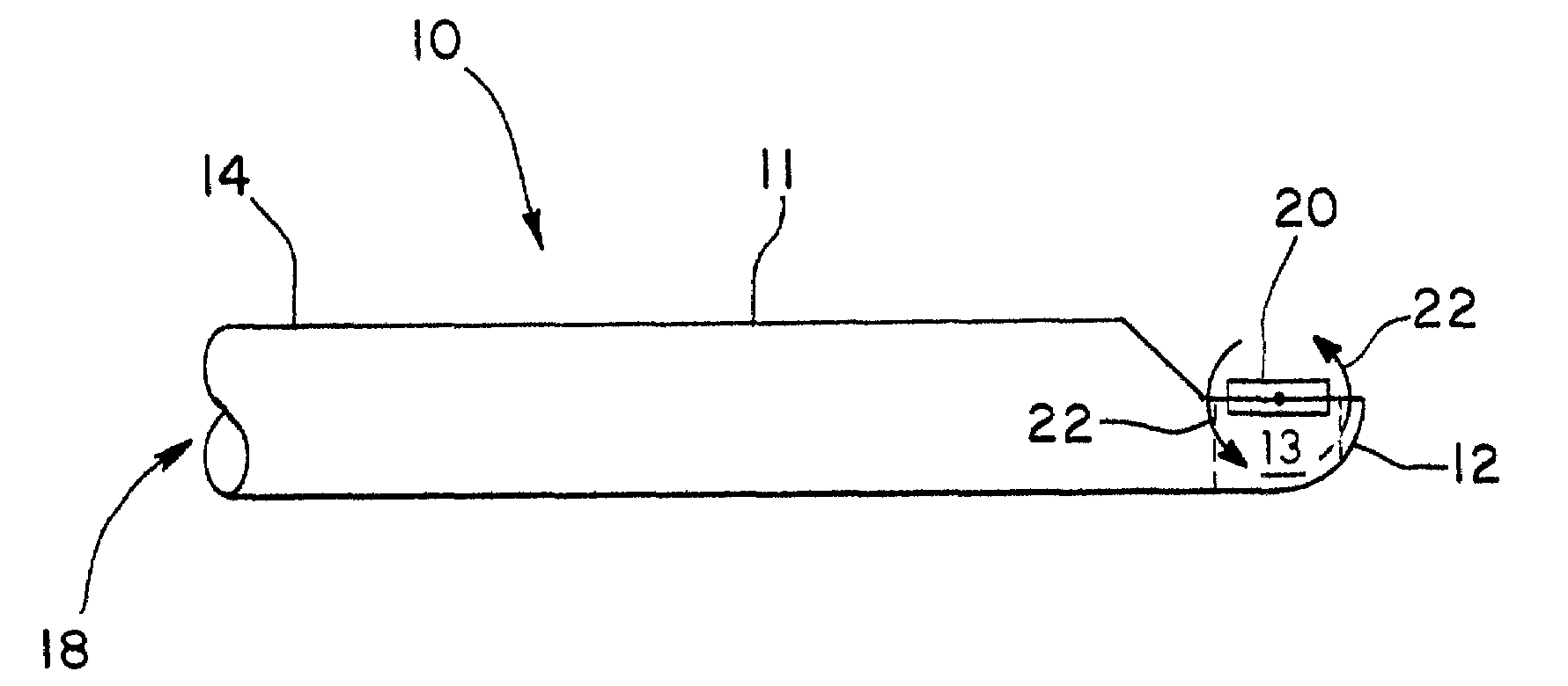
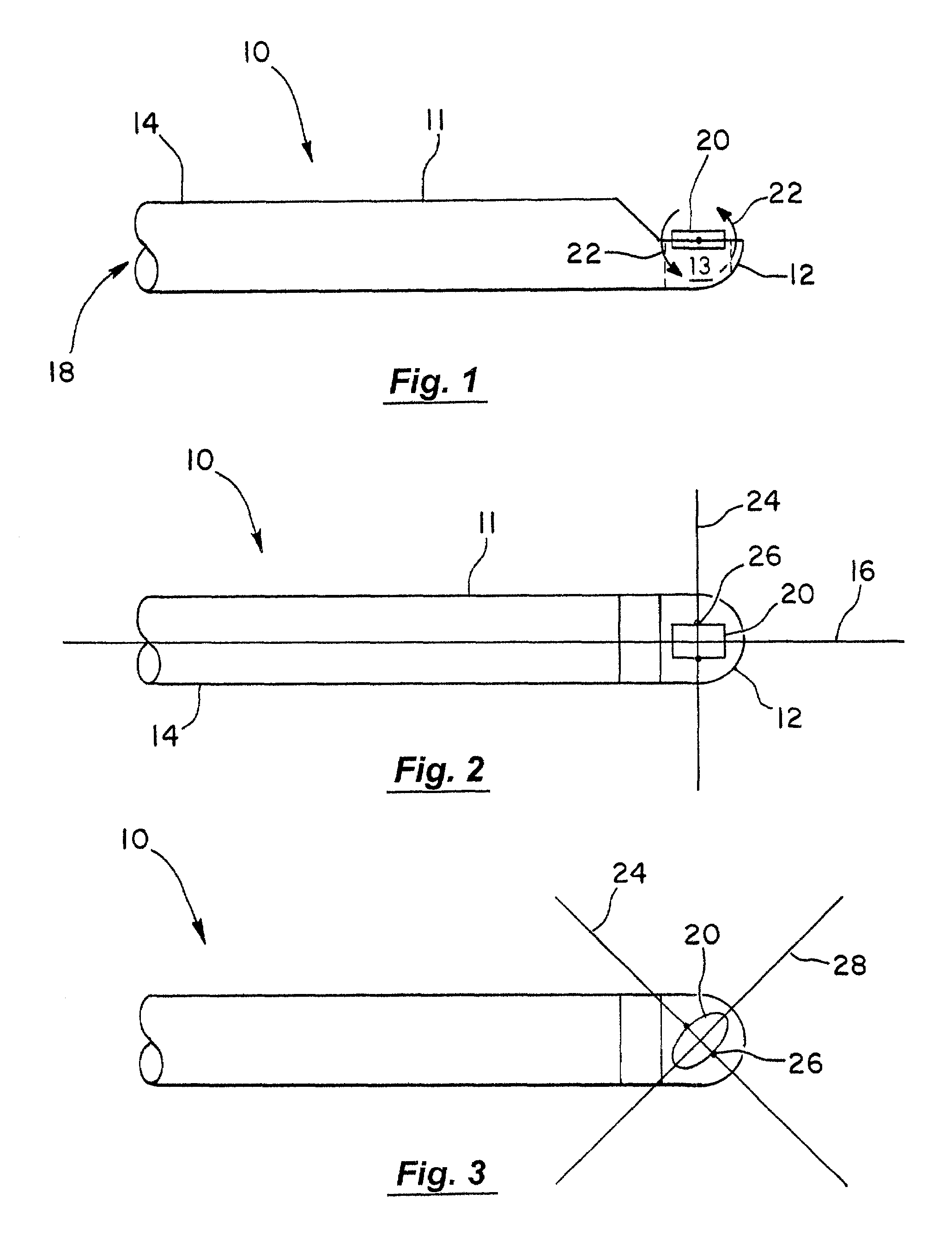
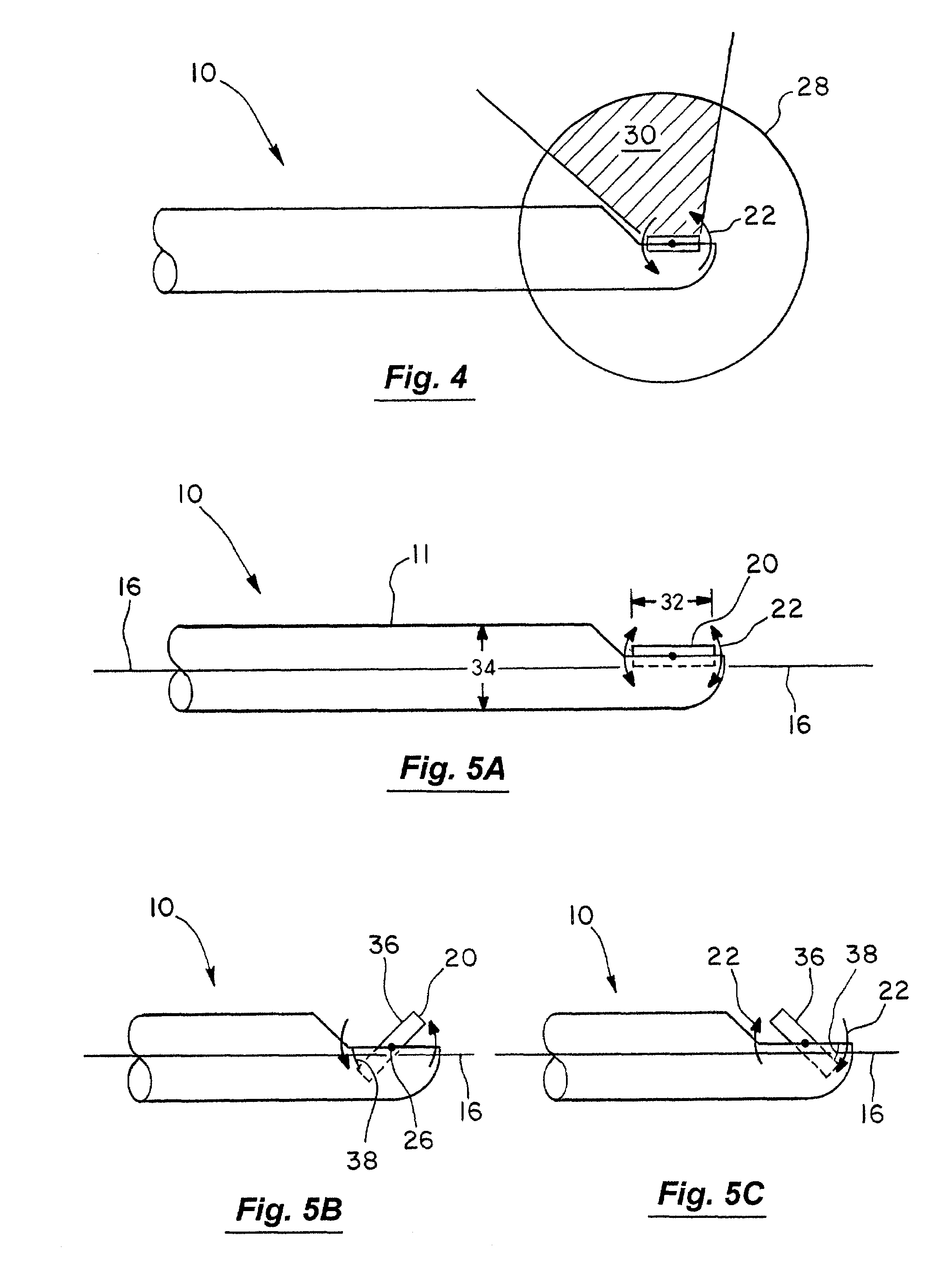
[0046]FIGS. 1 and 2 depict an imaging catheter 10 having a catheter body 11. Catheter body 11 has a distal end 12, a proximal end 14, and a longitudinal axis 16. A lumen 18 is provided within catheter body 11 and transducer 20 is rotatably coupled to distal end 12. Arrows 22 depict the rotation of transducer 20 with respect to distal end 12. While arrows 22 in FIG. 1 depict a counter-clockwise rotation, a clockwise rotation also may be used. Transducer 20 is rotatably coupled to catheter body 11 in a variety of manners. In one embodiment, transducer 20 is connected to distal end 12 using two rotatable attachment points 26 as shown in FIG. 2. Other attachment methods are within the scope of the present invention, some of which are discussed further in conjunction with FIG. 7.

[0047]As best seen in FIGS. 2 and 3, transducer 20 rotates about an axis of rotation 24 that is not coaxial with the catheter body longitudinal axis 16. As shown in FIG. 2, transducer 20 has axis of rotation 24 t...


PUM


Abstract

The present invention provides ultrasound imaging catheters, systems and methods for their use which will be particularly useful to monitor the positioning of ablation catheters. In one embodiment, an imaging catheter (10) includes a catheter body (11) having a distal end (12), a proximal end (14) and a longitudinal axis (16). A transducer (20) is rotatably coupled to the distal end. The transducer has an axis of rotation (24) that is at a non-zero angle relative to the catheter body longitudinal axis. Such a configuration provides an exemplary side-looking imaging catheter.

Description

BACKGROUND OF THE INVENTION[0001]The invention relates generally to the field of ultrasound imaging, and in particular, to the imaging of body lumens with ultrasound imaging catheters.[0002]Physicians make use of catheters today in medical procedures that are best performed by gaining access into interior regions of the body. For example, in electrophysiological therapy, ablation is used to treat cardiac rhythm disturbances. Such a therapy may be used, for example, to treat atrial fibrillation by forming long, thin lesions of different curvilinear shapes in heart tissue.[0003]During these procedures, a physician steers a catheter through a vein or artery into the interior region of the heart that is to be treated. An ablation element carried on the distal end of the catheter is positioned near the tissue that is to be ablated. For such treatments, the delivery of ablating energy must be closely governed to avoid incidence of tissue damage and coagulum formation. Further, the ablatio...

Claims


Application Information

Patent Timeline
IPC IPC(8): A61B8/14A61B8/00A61B5/11
CPCA61B8/0841A61B8/12A61B8/4461A61B8/445
Inventor SUORSA, VEIJO T.BELEF, W. MARTINBEYHAN, NIYAZIMAMAYEK, DONALD S.
Owner BOSTON SCI SCIMED INC
Why Eureka
Try Eureka