Power supply apparatus and high frequency circuit system

a power supply apparatus and high frequency circuit technology, applied in the direction of dielectric amplifiers, electric discharge tubes, travelling-wave tubes, etc., can solve the problems of large area, large area for mounting apparatus b>70/b>, and take a long time to reach, etc., to achieve the effect of improving work safety

Inactive Publication Date: 2009-02-10
NEC NETWORK & SENSOR SYST
View PDF4 Cites 7 Cited by
  • Summary
  • Abstract
  • Description
  • Claims
  • Application Information

AI Technical Summary

Benefits of technology

[0019]It is therefore an object of the present invention to provide a power supply apparatus which is capable of discharging charges accumulated in the power supply apparatus during testing and maintenance without using large-size parts, while improving the work safety, and a high frequency circuit system which comprises the power supply apparatus.
[0022]Therefore, the electric charges accumulated on the commuting capacitors can be discharged only by adding a small number of parts to a conventional circuit without the need to employ large discharge bleeder resistors. Consequently, the present invention can improve the safety of operations during testing and maintenance of the electron tube while limiting an increase in the size of the mounting area.

Problems solved by technology

This causes a problem that it takes a long time until helix voltage Ehel and collector voltage Ecol become sufficiently low after the operation of power supply apparatus 70 is stopped.
This causes a problem that large areas are needed for mounting discharge bleeder resistors R1, R2 which are mainly used only for testing and maintenance.
However, incorporating ground rod 75 into power supply apparatus 70 creates the problem that a larger area for mounting apparatus 70 is required.

Method used


Image

  • Power supply apparatus and high frequency circuit system
  • Power supply apparatus and high frequency circuit system
  • Power supply apparatus and high frequency circuit system

Examples


Embodiment Construction

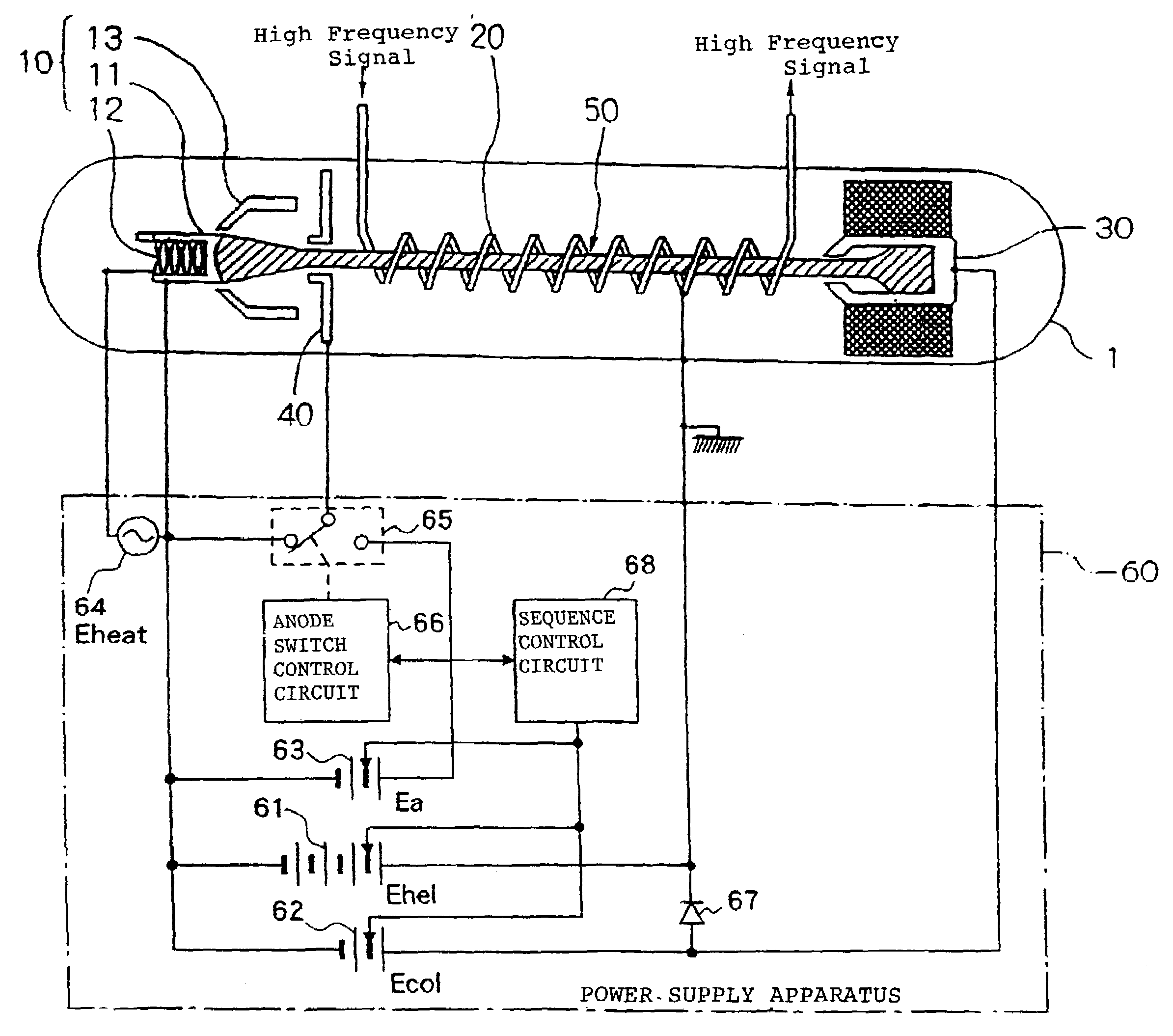
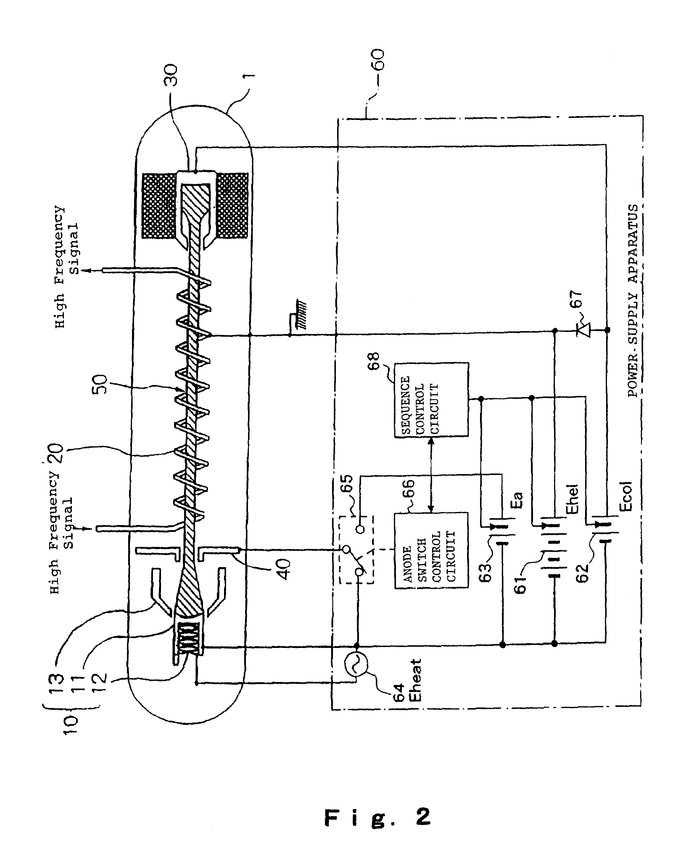
[0028]FIG. 2 is a block diagram illustrating an exemplary configuration of a power supply apparatus according to the present invention, and FIG. 3 is a circuit diagram illustrating an embodiment of an anode switch shown in FIG. 2. In FIG. 2, traveling-wave tube 1 and components thereof are designated the same reference numerals as those in FIG. 1 which has been referred to in the description of the prior art.

[0029]As illustrated in FIG. 2, power supply apparatus 60 of the present invention, like the conventional power supply apparatus, comprises helix power supply 61 for supplying a negative DC voltage (helix voltage Ehel) to cathode electrode 11 of electron gun 10 on the basis of the potential applied to helix 20, collector power supply 62 for supplying a positive DC voltage (collector voltage Ecol) to collector electrode 30 on the basis of the potential applied to cathode electrode 11, anode power supply 63 for supplying a positive DC voltage (anode voltage Ea) to anode electrode ...


PUM


Abstract

A power supply apparatus for supplying predetermined supply voltages respectively to an anode electrode, a cathode electrode, a collector electrode, and a helix of an electron tube. The power supply apparatus comprises an anode switch for turning on / off the anode voltage output, and an anode switch control circuit for controlling the on / off operation of the anode switch such that a pulsed anode voltage is repeatedly applied to the anode electrode a plurality of times at a predetermined period when operation of a helix power supply and a collector power supply is stopped.

Description

[0001]This application is based upon and claims the benefit of priority from Japanese Patent Application No. 2006-022851 filed on Jan. 31 2006, the content of which is incorporated by reference.BACKGROUND OF THE INVENTION[0002]1. Field of the Invention[0003]The present invention relates to a power supply apparatus for supplying predetermined supply voltages to a traveling-wave tube used to amplify and oscillate a high frequency signal, and a high frequency circuit system which comprises the power supply apparatus.[0004]2. Description of the Related Art[0005]A traveling-wave tube, a klystron and the like are electron tubes for amplifying or oscillating a high frequency signal by means of the interaction between an electron beam that is emitted from an electron gun and a high frequency circuit. For example, as illustrated in FIG. 1, traveling-wave tube 1 comprises electron gun 10 for emitting electron beam 50, helix 20 which is a high frequency circuit for causing electron beam 50 emi...

Claims


Application Information

Patent Timeline
Patent Type & Authority Patents(United States)
IPC IPC(8): H01J25/34
CPCH01J23/34
Inventor KOBAYASHI, JUNICHIFUJIWARA, EIJI
Owner NEC NETWORK & SENSOR SYST
Why Eureka
Try Eureka