Electronically controlled throttle valve unit

a technology of electronic control and throttle valve, which is applied in the direction of engine controllers, mechanical equipment, machines/engines, etc., can solve the problems of inability to accelerate the vehicle, difficulty in driving to the breakdown lane or to the repair plant, and inability to achieve the desired valve opening amount, etc., to achieve high setting freedom of valve opening characteristics, simple and inexpensive structure, and high durability

Inactive Publication Date: 2009-02-17
SUZUKI MOTOR CORP
View PDF14 Cites 4 Cited by
  • Summary
  • Abstract
  • Description
  • Claims
  • Application Information

AI Technical Summary

Benefits of technology

[0014]The present invention was conceived in consideration of the circumstances mentioned above and an object of the invention is to provide an electronically controlled throttle valve unit having a highly durable, simple, inexpensive and compact configuration and structure and capable of opening / closing the throttle valve mechanically according to a driver's intention at a time of trouble of an actuator or the like and having a high setting freedom of the valve opening characteristics, and in addition, at the time of normal operation of the actuator, smooth electronic control of the throttle valve can be achieved.
[0024]According to the electronically controlled throttle valve unit of the present invention, the mechanical valve opening / closing mechanism is provided, the throttle valve can be opened / closed mechanically according to a driver's intention when the actuator or the like is in trouble, thereby enabling driving for emergency or continuing to drive securely. The mechanical valve opening / closing mechanism has a simple and compact structure, and the setting freedom of the valve opening characteristics can be achieved when the throttle valve is mechanically opened / closed.
[0025]If the actuator is in trouble when the throttle valve is opened, the throttle valve can be closed quickly and securely according to the driver's intention. Further, upon the normal operation, the mechanical valve opening / closing mechanism can be prevented from affecting the control of the throttle valve, thereby achieving a smooth throttle valve control.

Problems solved by technology

As a result, thereafter, the vehicle cannot be accelerated, and it is difficult for the vehicle to drive for emergency to breakdown lane or to drive to a repair plant, for example.
However, in the electronically controlled throttle valve unit disclosed in the Patent Publication 1, when the actuator is in trouble, connection / disconnection of the first clutch and the second clutch need to be executed, and accordingly, it is necessary to cope with an abnormality in the clutch control system.
In addition, in the electronically controlled throttle valve unit disclosed in the Patent Publication 2, since the throttle valve shaft is operated in a direction of opening the valve through the coil spring interposed between the first lever and the second lever, there is a fear that a desired valve opening amount may not be achieved due to aging of the coil spring.
Furthermore, the electronically controlled throttle valve units of the Patent Publications 1 and 2 have such a defect that the number of their components is increased, and hence, their structure is made complicated, thus increasing manufacturing cost and easily inducing troubles.

Method used


Image

  • Electronically controlled throttle valve unit
  • Electronically controlled throttle valve unit
  • Electronically controlled throttle valve unit

Examples


Embodiment Construction

[0037]Hereinafter, the preferred embodiments of the present invention will be described with reference to the accompanying drawings. Further, it is to be noted that terms “upper”, “lower”, “right”, “left” and like terms are used herein with reference to the illustration of the drawings or in a usual installation state of an equipment including a throttle valve unit.

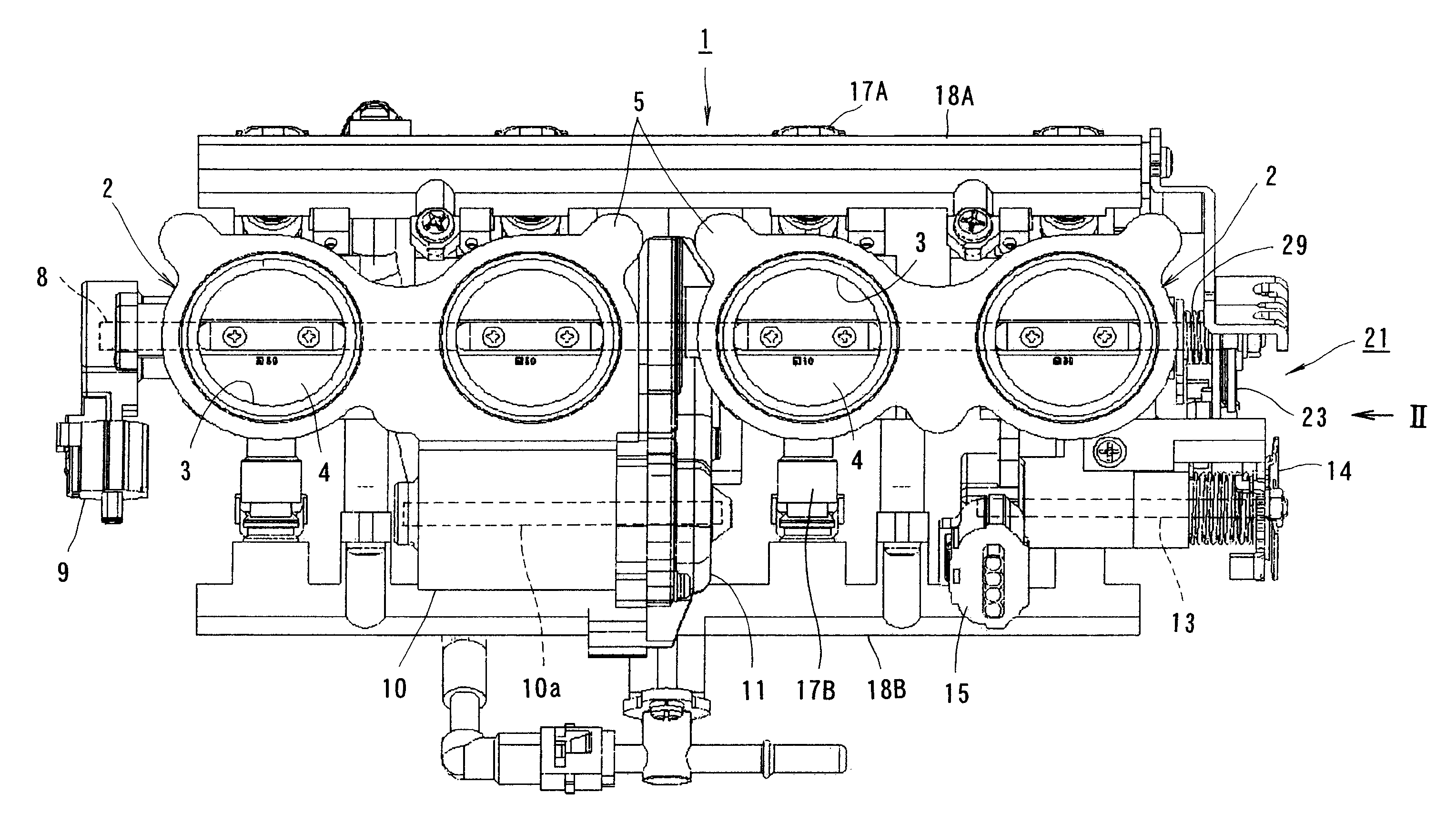
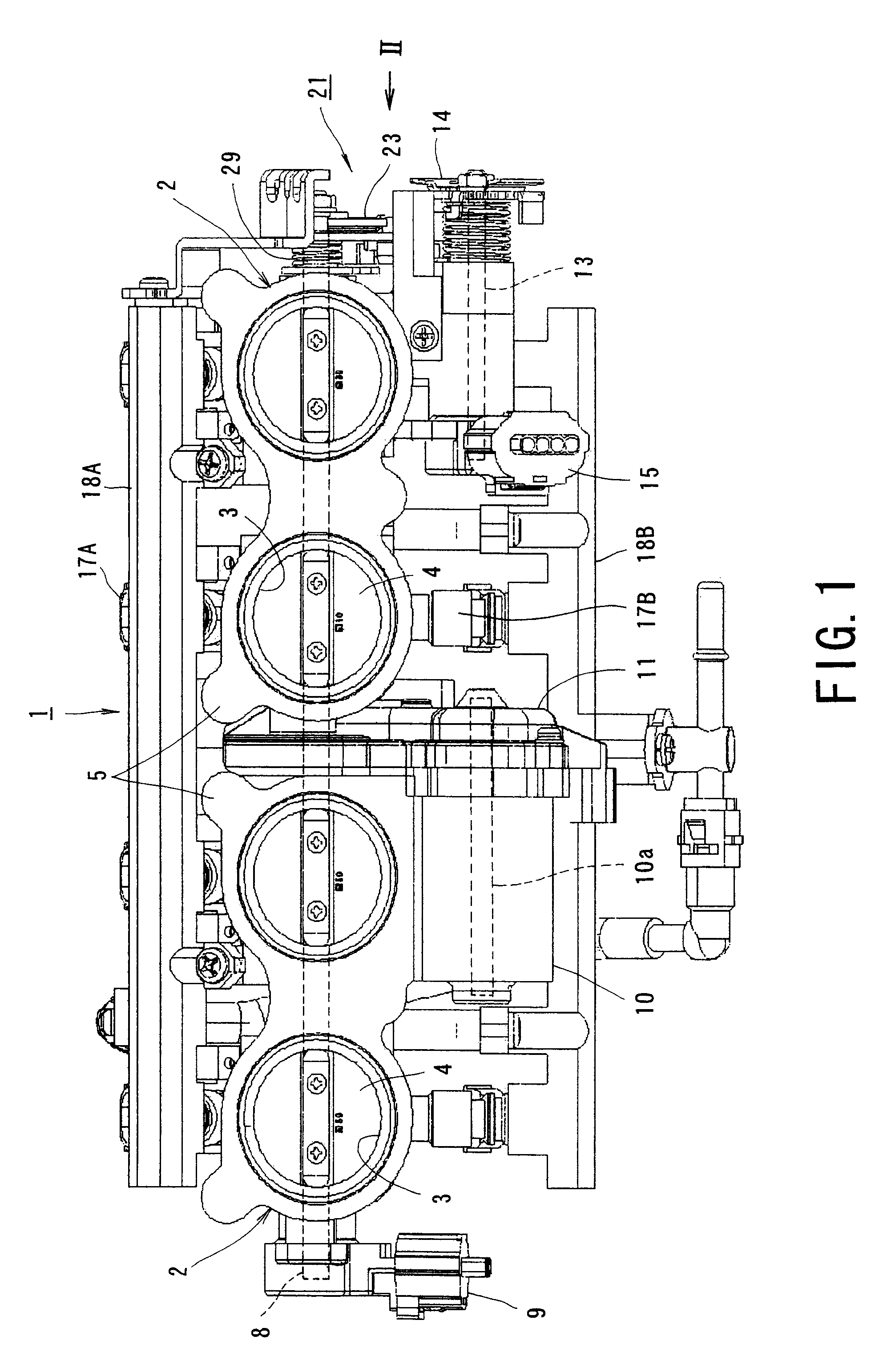
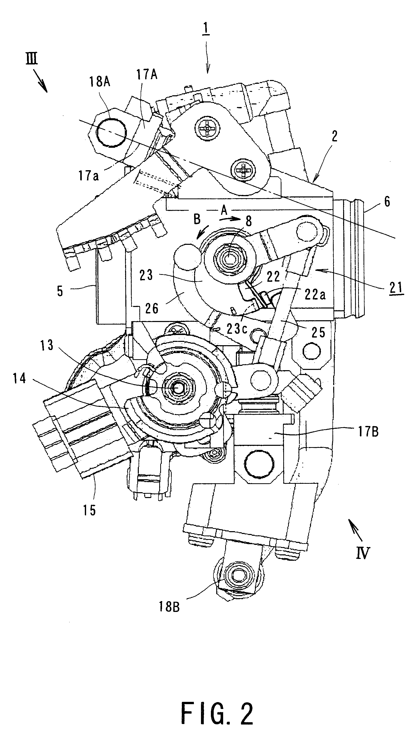
[0038]With reference to FIGS. 1 to 4, an electronically controlled throttle valve unit 1 is installed on, for example, a parallel four-cylinder engine of motorcycle and includes two units of twin throttle body 2 aligned in the vehicle width direction so as to form four throttles. In each throttle body 2, two intake air passages 3 are formed, the four intake air passages 3 are arranged in parallel to each other and a circular throttle valve 4 is provided for each intake air passage 3 in a manner so as to be opened or closed.

[0039]A connection flange 5 for connecting to an air cleaner side is formed at an end portion on the...


PUM


Abstract

An electronically controlled throttle valve unit includes a valve shaft supported by a throttle body, a throttle valve provided on the valve shaft rotatably therewith, an actuator for controlling the valve shaft, and a mechanical valve opening / closing mechanism. The mechanical valve opening / closing mechanism comprises: a valve lever provided on the valve shaft rotatably therewith; a cam lever supported rotatably with respect to the valve shaft so as to be directly operated through a throttle operation; and a link lever supported rotatably by the throttle body and transmitting a rotation of the cam lever in a direction of opening the throttle valve to the valve lever so as to rotate the valve lever and the valve shaft in a throttle valve opening direction with a predetermined rotation angle characteristics.

Description

CROSS-REFERENCE TO RELATED APPLICATIONS[0001]This application is an Application based upon and claiming the benefit of priority to Japanese Patent 2007-113134, filed on Apr. 23, 2007, the contents of which are incorporated herein by reference.BACKGROUND OF THE INVENTION[0002]1. Field of the Invention[0003]The present invention relates to an electronically controlled throttle valve unit for controlling opening / closing (opening and / or closing) operation of throttle valves by an actuator such as an electric motor, particularly, capable of operating a throttle on an emergency by opening / closing the throttle valve through throttle operation of a driver when the actuator is in trouble.[0004]2. Related Art[0005]In recent years, conventional carburetor type fuel supply system of the motorcycle has been replaced by that of fuel injection type, which is more highly efficient. At the same time, the conventional mechanical type throttle unit, which transmits a motion of a throttle grip directly...

Claims


Application Information

Patent Timeline
Patent Type & Authority Patents(United States)
IPC IPC(8): F02D9/10
CPCF02D9/1065F02D9/1095F02D11/10F02D11/107
Inventor ITAGAKI, KATSUHIKO
Owner SUZUKI MOTOR CORP
Why Eureka
Try Eureka