Cardiovascular access catheter with slit valve

a technology of access catheter and slit valve, which is applied in the field of medical catheters, can solve the problems of unsatisfactory and dangerous continuous fluid communication, clamping can impose undesirable wear on the catheter body, and the continuous fluid communication provided by the catheter must be curtailed, so as to reduce the injury of patients and improve the durability and reliability of the performance of long-term cardiovascular access catheters

Active Publication Date: 2009-02-17
CR BARD INC
View PDF39 Cites 35 Cited by
  • Summary
  • Abstract
  • Description
  • Claims
  • Application Information

AI Technical Summary

Benefits of technology

[0023]In one aspect of the present invention the durability and reliability of the performance of long-term cardiovascular access catheters is increased while minimizing injury to patients arising from use thereof.

Problems solved by technology

When the catheter is not being used, however, this continuous fluid communication is undesirable and dangerous.
Therefore, the continuous fluid communication to the cardiovascular system provided by the catheter must be curtailed when the catheter is not in use.
A tube clamp can impose undesirable wear on a catheter body and may be released unintentionally.
In addition, while a tube clamp prevents net fluid flow through the catheter, a tube clamp does not prevent fluid transfer between the cardiovascular system of the patient and the lumen of the catheter body through the open distal end thereof.
Small volumes of blood might enter the stagnant column of fluid and clot, possibly leading to various complications that are dangerous to the patient.
The clotting process can completely obstruct the otherwise permanently open distal end of the catheter or the interior of the associated lumen.
An obstruction renders the catheter useless and requires removal of the obstructed catheter and implantation of a replacement catheter.
When the catheter lumen is only partially obstructed by the clot, the risk to the patient can be severe.
Catheters are susceptible to tearing during insertion into or removal from the body of the patient.
In addition, the portion of the catheter implanted in the body of the patient can tear at certain locations where the catheter is subjected to localized stress within the body.
The extracorporeal portion of an implanted catheter can tear due to mishandling.
Catheters also are susceptible to bursting when fluids are injected through the catheter under pressure.

Method used


Image

  • Cardiovascular access catheter with slit valve
  • Cardiovascular access catheter with slit valve
  • Cardiovascular access catheter with slit valve

Examples


first embodiment

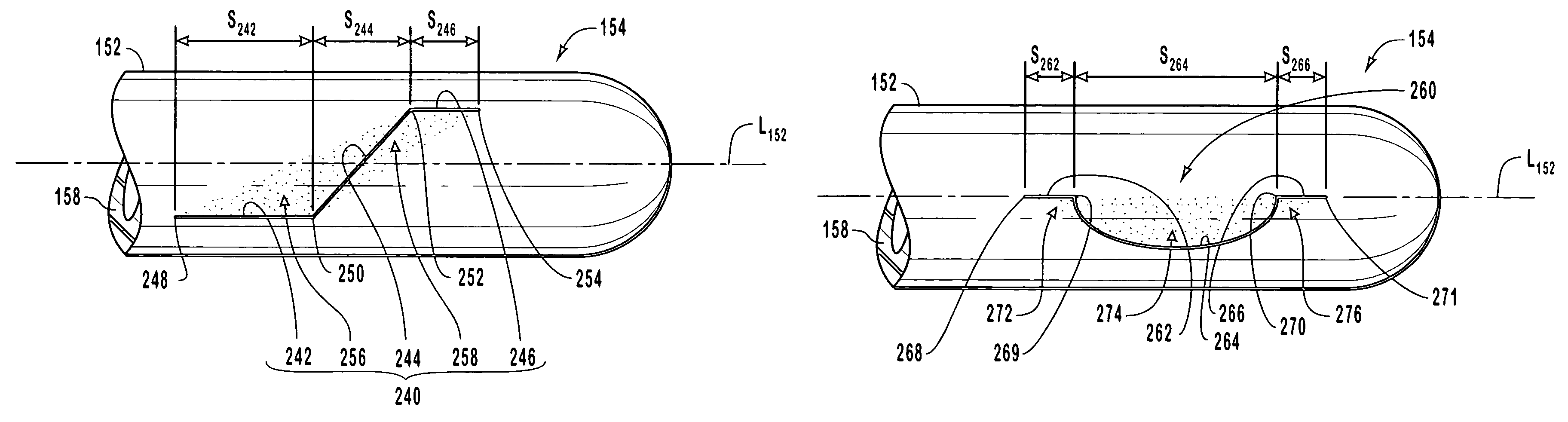
[0108]FIG. 10 is an enlarged plan view of distal portion 84 of catheter body 82 shown in FIG. 9 showing a slit valve incorporating teachings of the present invention. Catheter body 82 is seen to have a longitudinal axis L82 and to terminate in a closed distal tip 94. Distal portion 84 of catheter body 82 includes a cylindrical circumferential outer wall 88 and a semispherical terminal endwall 96 that is continuous with outer wall 88. A slit valve 110 is formed through outer wall 88 in distal portion 84 of catheter body 82.

[0109]Slit valve 110 includes a planar slit 112 that is disposed in a slit orientation plane P1 shown on edge in FIG. 10. Planar slit 112 extends longitudinally through outer wall 88 at an acute axial deviation angle A1 relative to longitudinal axis L82 of catheter body 82. Broadly, acute axial deviation angle A1 can be in a range from about 10° to about 80°. More narrowly, acute axial deviation angle A1 can be in a range from about 20° to about 70°. Most narrowly,...

second embodiment

[0133]FIG. 15 is a cross-sectional view of distal portion 84 of catheter device 80 of FIG. 10 taken along section line 11-11 shown therein illustrating a slit valve 140 that incorporates teachings of the present invention. Slit valve 140 includes a planar slit having a slit length L2 that is measured in the plane of slit valve 140 along outer surface 92 of catheter body 82 between outer proximal endpoint 124a and outer distal endpoint 130a, which are disposed on outer surface 92 of catheter body 82. Slit length L2 is shorter than slit length L1 shown in FIG. 11 and approaches the magnitude of thickness T1 of outer wall 88.

third embodiment

[0134]FIG. 16 is a cross-sectional view like that of FIG. 15 illustrating a slit valve 141 that incorporates teachings of the present invention. Slit valve 141 includes a planar slit having a slit length L3 that is measured in the plane of slit valve 141 along outer surface 92 of catheter body 82 between outer proximal endpoint 124b and outer distal endpoint 130b, which are disposed on outer surface 92 of catheter body 82. Slit length L3 is approximately ten times thickness T1 of outer wall 88.

[0135]Planar slit 112 of slit valve 110 shown in FIG. 12, the planar slit of slit valve 140 shown in FIG. 15, and the planar slit of slit valve 141 shown in FIG. 16 are disposed in slit orientation plane P1 about longitudinal positioning point I1 such that the slits are symmetric about unique diameter D1. For example, the section of slit length L3 shown in FIG. 16 extending between outer proximal endpoint 124b and the intersection of unique diameter D1 with outer surface 92 of catheter body 82...


PUM


Abstract

Two-way, three-position and one-way, two-position slit valves in cardiovascular access catheters with closed distal ends have slit geometries configured to overcome adhesion between opposed abutting slit faces, when pressure differentials are applied between the interior and the exterior of the catheter. Portions of the slit are oriented at a non-zero angle relative to the longitudinal axis of the catheter causing shear forces to be generated in abutting slit faces. Shear forces arise from tangential, radial, or longitudinal stresses generated in the catheter body. Slit geometries are planar or curved or include multiple end-to-end connected slit subsections. If a slit partially circumscribes a portion of the adjacent outer wall of the catheter body, restraint to outward and inward movement on that portion is reduced. Slit valves are configured to open inwardly to aspirate fluids, to open outwardly to infuse fluids, or both.

Description

BACKGROUND[0001]1. Field of the Invention[0002]This invention pertains to medical catheters, and more particularly to catheters adapted for transcutaneous or complete implantation in the body of a human patient, thereby to provide access through the catheter to the cardiovascular system of the patient.[0003]2. State of the Art[0004]Catheters are commonly used to access the cardiovascular system of a patient from outside the body of the patient. The cardiovascular access afforded by such catheters permits the monitoring of blood pressure, the aspiration of blood, and the infusion of medicaments and nutrients at various locations within the cardiovascular system. For example, catheters can provide access to the central regions of the cardiovascular system in the vicinity of the high volume blood flow passageways immediately interconnected with the heart.[0005]Cardiovascular access catheters typically include an elongated, flexible catheter tube having one or more fluid flow passageway...

Claims


Application Information

Patent Timeline
Patent Type & Authority Patents(United States)
IPC IPC(8): A61M5/00
CPCA61M25/0075
Inventor DIFIORE, ATTILIO E.
Owner CR BARD INC
Why Eureka
Try Eureka