Light controller and imaging apparatus

a technology which is applied in the field of light controller and imaging apparatus, can solve the problems of incongruity, difficult to see patterns or the like under such influences as false signals, and achieve the effects of reducing the generation of false color signals, preventing false color signals and moirés, and reducing blurring effects

Inactive Publication Date: 2009-02-17
SONY CORP
View PDF9 Cites 8 Cited by
  • Summary
  • Abstract
  • Description
  • Claims
  • Application Information

AI Technical Summary

Benefits of technology

[0023]The present inventor zealously studied improvement of the above-mentioned problems of the generation of false color signals and moirés, and, for the first time, knew that in some manners of mounting the liquid crystal element and the polarizing plate, which constitute the light control device, the deviation of the intensity of the separated light occurs and the optical lowpass filter's effect of preventing the generation of false color signals is reduced. The present inventor has attained the invention by ascertaining that it is extremely effective for the improvement thereof to place each of the polarization axis of the polarizing plate, the direction of the liquid crystal alignment of the liquid crystal element, and the light ray separation directions of the birefringent plates which constitute the optical lowpass filter, in an optimal direction, that is, to have the light ray separation directions of said birefringent plates and the direction of the polarization axis of said polarizing plate wholly differ from one another.
[0025]Therefore, the invention can enhance the optical functions of the light control device and the imaging device and is extremely effective in enhancing the performance, the quality of an image, and the reliability of the device.

Problems solved by technology

Consequently, an image of the pattern or the like is very hard to see under such influences of false signals.
This causes troubles that false color signals and moirés occur when geometrical patterns (of, for example, striped clothes, and tiled walls of buildings) finer than the periodic arrangement of the CCDs are shown, and that images of the patterns causes feeling of incongruity.

Method used


Image

  • Light controller and imaging apparatus
  • Light controller and imaging apparatus
  • Light controller and imaging apparatus

Examples


example 1

[0066]First, an example of the light control device using the guest-host liquid crystal (GH) cell is described.

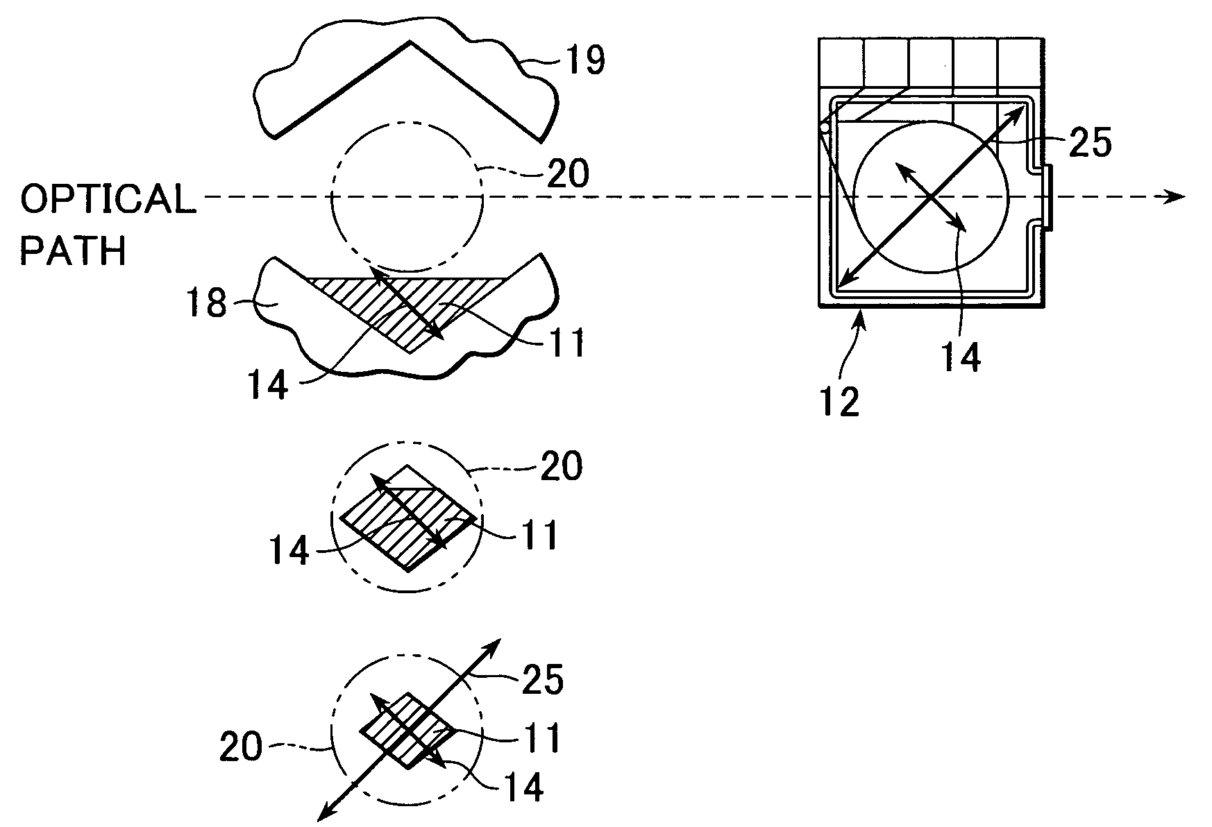
[0067]The light control device according to the invention is disposed at a front position of the optical lowpass filter comprising said plurality of birefringent plates, sequentially disposed in the optical path of the imaging system of the imaging device, and has the polarizing plate 11 and the GH cell 12, which are arranged in this order.

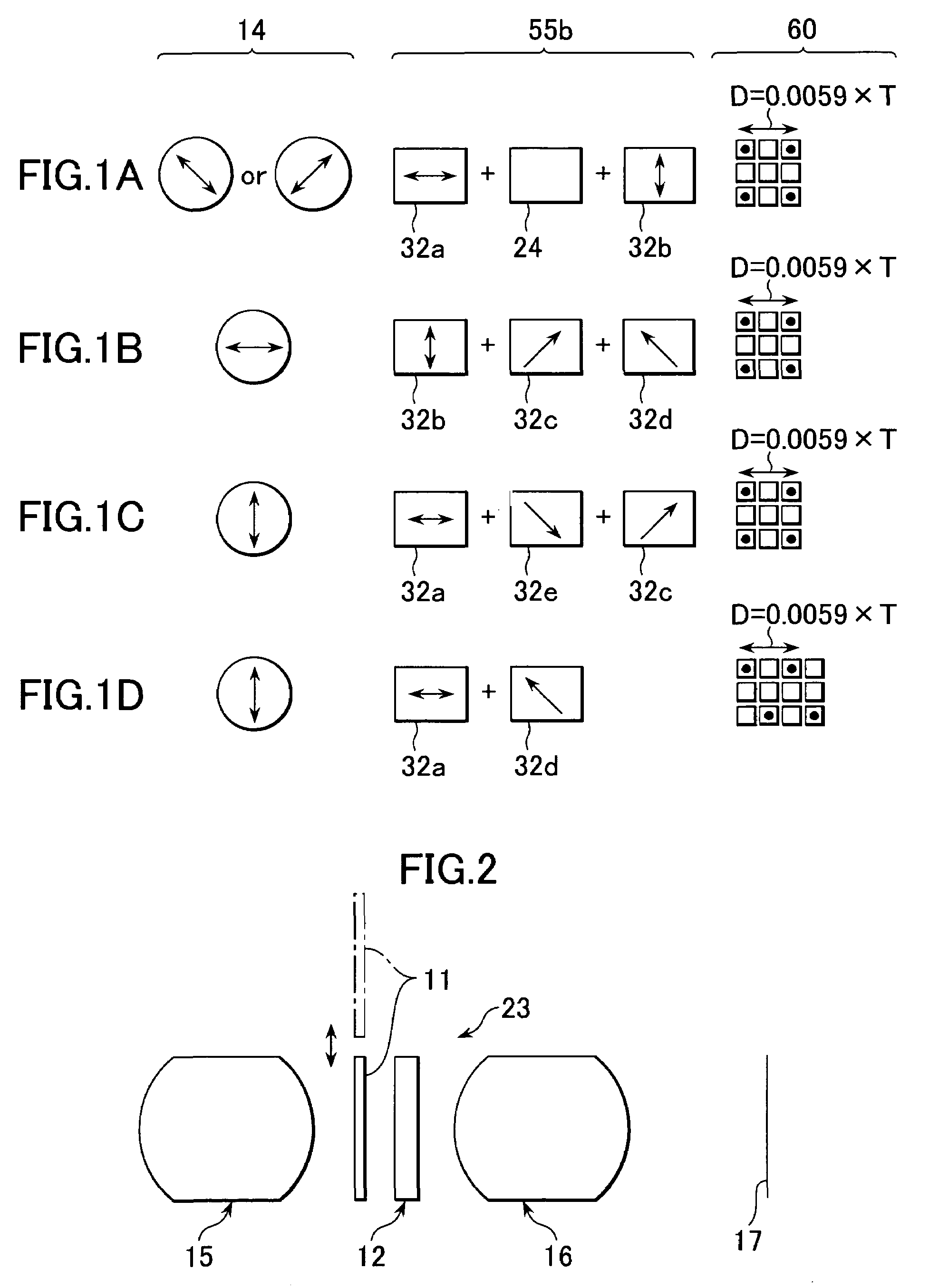
[0068]Incidentally, as shown in FIG. 1A, the optical lowpass filter 55b comprises a birefringent plate 32a whose light ray separation direction from the light incidence side is a horizontal direction, a quarter-wave phase difference plate (whose thickness is, for example, about 0.5 mm) 24, and a birefringent plate 32b whose light ray separation direction is a perpendicular direction, and the light ray separation directions of the birefringent plates 32a and 32b, and the direction of the polarization asis 14 of the polarizing plate 11 whol...

example 2

[0080]The differences between Example 2 and Example 1 reside in that the members constituting the optical lowpass filter of Example 2 differ from those of Example 1, and that the direction of the polarization axis of the polarizing plate and the direction of the liquid crystal orientation of the GH cell are changed so as to correspond to this optical lowpass filter.

[0081]That is, in Example 2, as shown in FIG. 1B, the optical lowpass filter 55b comprises a birefringent plate 32b whose light ray separation direction is a perpendicular direction, and two birefringent plates 32c and 32d, whose light ray separation directions are apart therefrom 45 degrees, and the light ray separation directions of the birefringent plates 32b, 32c and 32d, and the direction of the polarization axis 14 of the polarizing plate 11 completely differ one another.

[0082]Furthermore, the polarizing plate 11 was disposed so that the direction of the polarization axis 14 was a horizontal direction. That is, the ...

example 3

[0087]The differences between Example 3 and Example 1 reside in that the members constituting the optical lowpass filter of Example 3 differ from those of Example 1, and that the direction of the polarization axis of the polarizing plate and the direction of the liquid crystal orientation of the GH cell are changed so as to correspond to this optical lowpass filter.

[0088]That is, in Example 3, as shown in FIG. 1C, the optical lowpass filter 55b comprises a birefringent plate 32a whose light ray separation direction is a horizontal direction, and two birefringent plates 32e and 32c,whose light ray separation directions are apart therefrom 45 degrees, and the light ray separation directions of the birefringent plates 32a, 32e and 32c, and the direction of the polarization axis 14 of the polarizing plate 11 wholly differ one another.

[0089]Further, the polarizing plate 11 was disposed so that the direction of the polarization axis 14 was a perpendicular direction. That is, the device wa...


PUM

PropertyMeasurementUnit
angleaaaaaaaaaa
angleaaaaaaaaaa
angleaaaaaaaaaa

Abstract

An imaging apparatus is comprised of a light controller including a liquid crystal element and a polarizing plate located in front of an optical low-pass filter in the optical path of the imaging apparatus. The polarization direction of the polarizing plate and the orientation for the liquid crystal element are selectively chosen with respect to the rotation of the optical low pass filter elements in order to achieve a desired improvement in the device performance.

Description

[0001]This application claims priority to Japanese Patent Application No. JP2002-135164, filed May 10, 2002 which is incorporated herein by reference.TECHNICAL FIELD[0002]The present invention relates to a light control device, for example, for controlling a quantity of incident light and for outputting the light, and to an imaging device using this light control device.BACKGROUND ART[0003]Generally, a polarizing plate is used in a light control device using a liquid crystal cell. As this liquid crystal cell, for instance, a TN (Twisted Nematic) liquid crystal cell or a Guest Host (GH) liquid crystal cell is used.[0004]FIGS. 12A and 12B are schematic drawings each showing the principle of an operation of a conventional light control device. This light control device is constituted mainly by a polarizing plate 1 and a GH cell 2. The GH cell 2, which is not shown in the drawings, is sealed between two glass substrates, and has a working electrode and a liquid crystal alignment film (t...

Claims


Application Information

Patent Timeline
Patent Type & Authority Patents(United States)
IPC IPC(8): H04N5/225G02B5/30G02F1/13G02F1/1335G02F1/137G02F1/139G03B9/02H04N5/238
CPCG02F1/133528G02F1/13725H04N5/2254H04N5/238G02F2001/133531G02F1/133531H04N23/55H04N23/75G02F1/137G02F1/1335
Inventor YANAGIDA, TOSHIHARU
Owner SONY CORP
Why Eureka
Try Eureka