Method and system for data compression for storage of 3D comb filter data

a data compression and data technology, applied in the field of video signal processing, can solve the problems of significant vertical bandwidth, inconvenient storage, and loss, and achieve the effects of reducing storage requirements, eliminating aliasing, and reducing storage requirements

Active Publication Date: 2009-02-17
AVAGO TECH INT SALES PTE LTD
View PDF21 Cites 1 Cited by
  • Summary
  • Abstract
  • Description
  • Claims
  • Application Information

AI Technical Summary

Benefits of technology

[0026]Another aspect of the invention may provide a machine-readable storage, having stored thereon, a computer program having at least one code section executable by a machine, thereby causing the machine to perform the steps as described above for processing video signals having reduced storage requirements.
[0027]The system for processing video signals having reduced storage requirements may include at least one processor that band-limits an incoming video signal during combing, wherein the incoming video signal comprises a plurality of active and inactive video samples disposed within a plurality of video lines. The processor may store the active video samples disposed within at least a portion of the plurality of video lines. The processor may band-limit the incoming video signal to 6.75 MHz in order to eliminate aliasing. The processor may also store video samples utilized for eliminating edge effects, where the number of video samples may be associated with an upsampling filter tap count. The processor may comb the active video samples and may store a portion of the plurality of video lines.

Problems solved by technology

During separation of the luma and chroma components, there are three bandwidth directions that may incur losses in the separation process and in the separated signal.
However, vertical combing may result in a reduced vertical bandwidth.
In this case, there may be significant vertical bandwidth.
When the current line 334 and the previous line 332 are combed together, there may be significant error in both the luma and chroma.
This may produce combing artifacts in the obtained combed video signal.
Higher bandwidth in a given direction may cause combing in that direction to result in more incorrectly separated luma and chroma.
In instance where there is color changes or image movements between the buffered frames, the corresponding Y / C components for the buffered frames will be different and the results of combing would be incorrect.
Accordingly, 3D comb filters require a large or significant amount of video memory and excessive memory processing bandwidth requirements.
This large memory and excessive memory processing bandwidth requirements, along with the necessary motion detection processing, increases the cost associated with 3D comb filter solutions.

Method used


Image

  • Method and system for data compression for storage of 3D comb filter data
  • Method and system for data compression for storage of 3D comb filter data
  • Method and system for data compression for storage of 3D comb filter data

Examples


Embodiment Construction

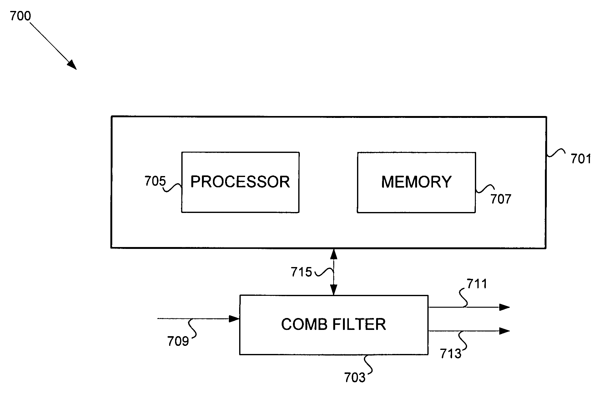
[0039]Certain aspects of the invention may be found in a method and system for processing video signal having reduced storage requirements. Since YC separation utilizing 3D combing requires that a plurality of successive frames be delayed in buffers for comparison, the memory and memory bandwidth requirements may be very high. Accordingly, one aspect of the invention provides a method for reducing the amount of data stored for YC separation during 3D combing. A reduction in the amount of data stored for YC separation during 3D combing may be achieved by storing or buffering data that is necessary for 3D combing. In this regard, a reduction in the amount of memory required and the amount of memory bandwidth utilized for YC separation during 3D combing may therefore be achieved through data compression.

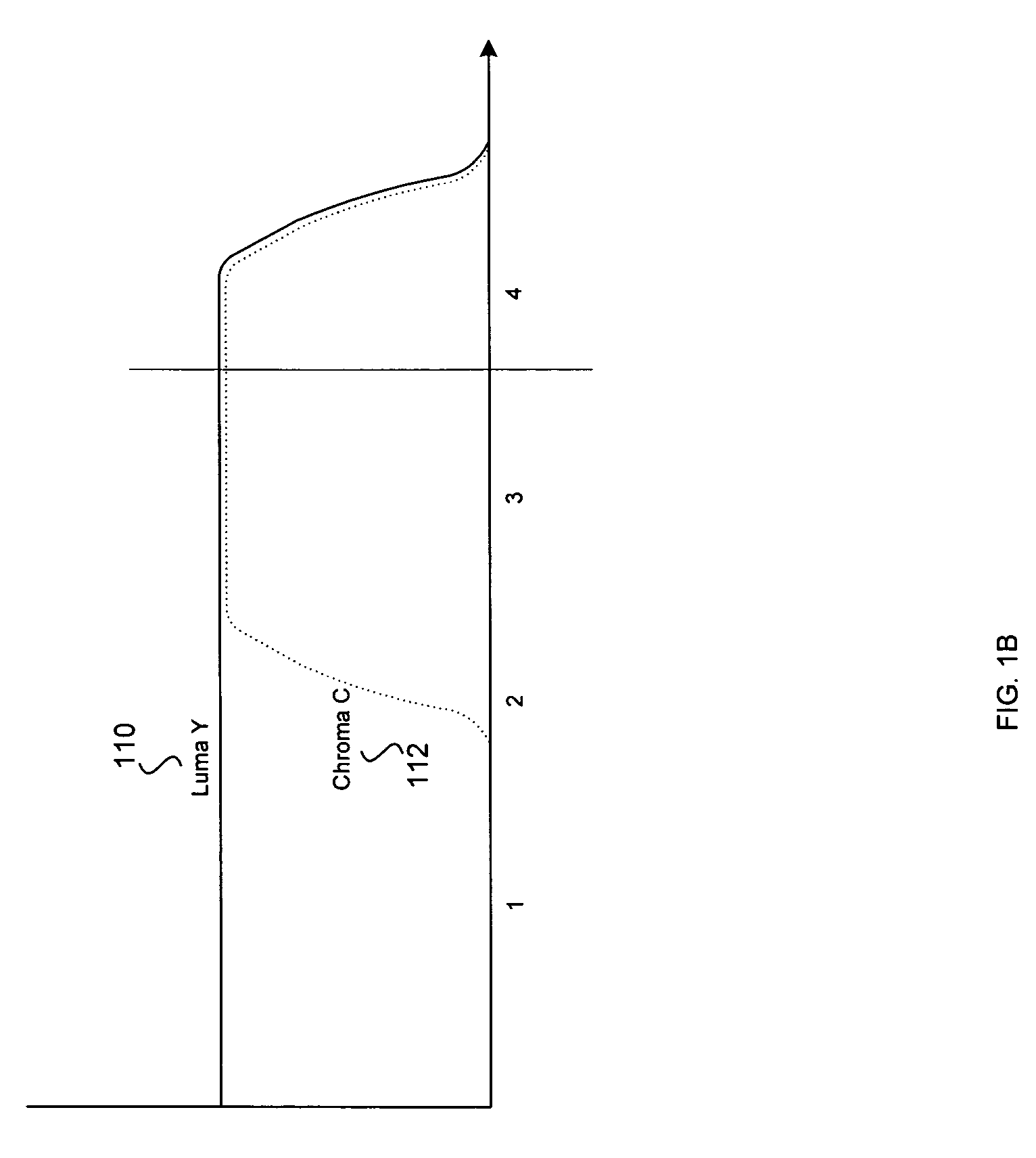
[0040]The NTSC standard limits the bandwidth of incoming signals to 4.2 MHz and the PAL standard limits the incoming signal to maximum of about 6.0 MHz. Given these bandwidth limitation...


PUM


Abstract

Methods and systems for data compression for storage of 3D comb filter data are disclosed. An incoming video signal may be band-limited during combing, where the incoming video signal may comprise a plurality of active and inactive video samples disposed within a plurality of video lines. The active video samples disposed within at least a portion of the plurality of video lines may be stored. The incoming video signal may be band-limited to 6.75 MHz, for example. Video samples utilized for eliminating edge effects may be stored. The number of video samples utilized for eliminating edge effects may be associated with an upsampling filter tap count. The active video samples may be combed. At least a portion of the plurality of video lines may be stored. The portion of the plurality of video lines may comprise active video lines.

Description

CROSS-REFERENCE TO RELATED APPLICATIONS / INCORPORATION BY REFERENCE[0001]This patent application makes reference to, claims priority to and claims benefit from U.S. Provisional Patent Application Ser. No. 60 / 542,588, entitled “DATA COMPRESSION FOR STORAGE OF 3D COMB FILTER DATA,” filed on Feb. 5, 2004, the complete subject matter of which is hereby incorporated herein by reference, in its entirety.[0002]This application makes reference to:[0003]U.S. application Ser. No. 10 / 943,267 filed Sep. 17, 2004;[0004]U.S. application Ser. No. 10 / 943,587 filed Sep. 17, 2004;[0005]U.S. application Ser. No. 10 / 943,593 filed Sep. 17, 2004;[0006]U.S. application Ser. No. 10 / 943,596 filed Sep. 17, 2004; and[0007]U.S. application Ser. No. 10 / 943,641 filed Sep. 17, 2004.[0008]The above stated applications are hereby incorporated herein by reference in their entirety.FIELD OF THE INVENTION[0009]Certain embodiments of the invention relate to processing of video signals. More specifically, certain embodim...

Claims


Application Information

Patent Timeline
Patent Type & Authority Patents(United States)
IPC IPC(8): H04N9/77H04N9/78H04N9/64
CPCH04N9/78
Inventor DELANGHE, BRADMOVSHOVICH, ALEKSANDR
Owner AVAGO TECH INT SALES PTE LTD
Why Eureka
Try Eureka