
Rotational control assembly in packaging machines

a technology of rotating control and packaging machine, which is applied in the direction of mechanical control devices, gearing, caps, etc., can solve the problems of affecting the quality of finished packages, affecting the operation of mechanical components and assemblies, and film tucking can damage the die beads, so as to prevent damage to other mechanical components

Inactive Publication Date: 2009-02-24
BEMIS COMPANY INC
View PDF8 Cites 2 Cited by
  • Summary
  • Abstract
  • Description
  • Claims
  • Application Information

AI Technical Summary

Benefits of technology

The present invention provides an assembly for controlling the rotational movement of a die wheel in packaging machinery to prevent damage to other mechanical components and systems operationally interconnected to the die wheel. The assembly includes a first component operationally interconnected to both the die wheel and camshaft, and a second component physically connected to both the first component and the framework of the packaging machine. The second component is detachably mounted to the framework. This invention prevents damage to the die wheel and camshaft, which can save time and money.

Problems solved by technology

However, when power is removed to these machines, particularly after an emergency shut-down, the die wheel may respond by moving for short distances in the opposite direction.
This can result in damage to mechanical components and assemblies operationally interconnected to the die wheel.
For example, if the die wheel rotates backwards, the film tucker can damage the die beads by scratching or marring the surface of the die bead.
A damaged die bead surface will not allow hermetic seals to be formed in the food package and, therefore, adversely affect the quality of the finished package.

Method used


Image

  • Rotational control assembly in packaging machines
  • Rotational control assembly in packaging machines
  • Rotational control assembly in packaging machines

Examples


Embodiment Construction

[0012]Although specific embodiments of the present invention will now be described with reference to the drawings, it should be understood that such embodiments are by way of example only and merely illustrative of but a small number of the many possible specific embodiments which can represent applications of the principles of the present invention.

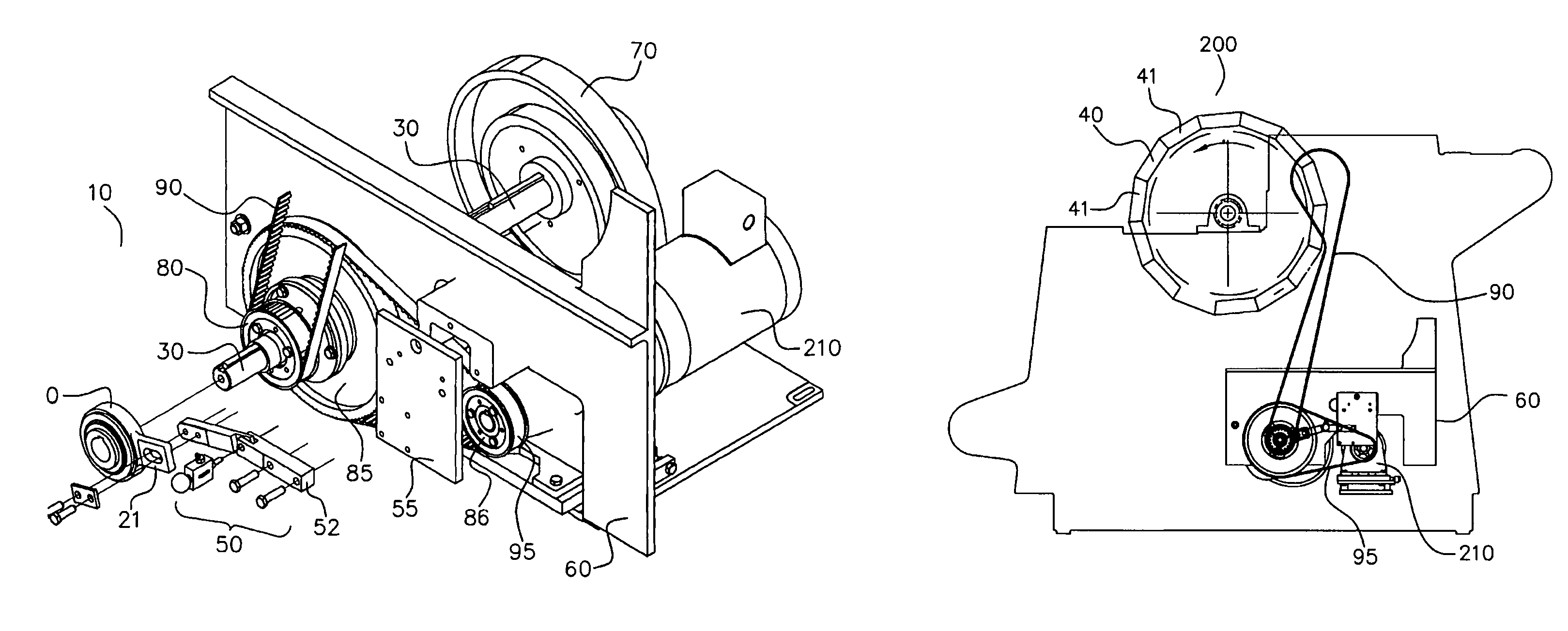
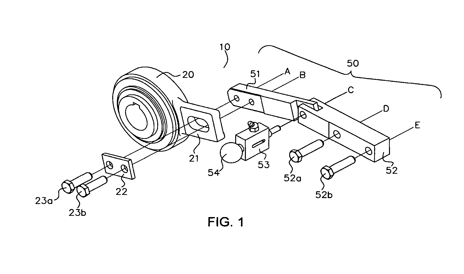
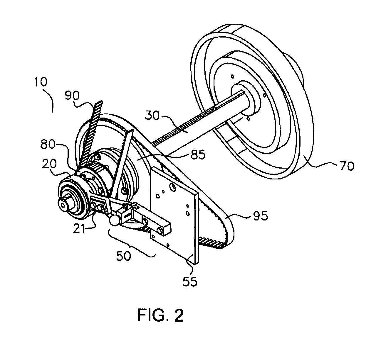
[0013]Referring now to the drawings, wherein similar characters designate corresponding parts throughout the several views, there is illustrated a preferred embodiment of an assembly for controlling the rotational movement of a die wheel in packaging machinery according to the present invention. Referring specifically to FIG. 1, there is illustrated schematically an exploded view of assembly 10 comprising a first component 20 and a second component 50. In this embodiment, first component 20 may further comprise an attachment member 21 for joining first component 20 to second component 50. It is within the scope of the present invention t...


PUM


Abstract

The present invention provides an assembly for controlling the rotational movement of a die wheel in packaging machinery and includes a first component operationally interconnected to both the die wheel and camshaft, and a second component physically connected to both the first component and the framework of the packaging machine wherein the second component is detachably mounted to the framework.

Description

TECHNICAL FIELD[0001]This invention relates to the field of packaging machinery. Specifically, the present disclosure is a system for controlling the rotational movement of a die wheel in packaging machinery.BACKGROUND OF THE INVENTION[0002]Packaging machinery for packaging food products such as cheese and meat, particularly, processed meat, such as bacon, are known in the art. In general, packaging machinery which are cam-operated are designed such that the rotating camshaft imparts rotational, horizontal and / or vertical motion to various camshaft components, i.e., cams, gears, sprockets and the like. These camshaft components, in turn, drive the various mechanical operations needed to produce a packaged food product.[0003]One type of cam-operated food packaging machine is a rotary die wheel packaging machine. Rotary die wheel packaging machines are designed to automatically perform multiple packaging operations around a central rotating die wheel. In this machine, package forming / ...

Claims


Application Information

Patent Timeline
Patent Type & Authority Patents(United States)
IPC IPC(8): B65B7/28
CPCB65B65/02Y10T74/1518Y10T74/2063Y10T74/1582Y10T74/2101
Inventor WEGNER, PAUL EDWARD
Owner BEMIS COMPANY INC
Learn More