Method for increasing the efficiency of a gas turbine system and gas turbine system suitable therefor

a gas turbine and efficiency technology, applied in steam engine plants, machines/engines, mechanical equipment, etc., can solve the problems of only being able to implement the reduction of waste gas temperature, high operating cost, and high heat loss of waste gas, so as to increase the efficiency of existing systems, improve the efficiency of the system, and increase the efficiency of gas turbine systems.

Active Publication Date: 2009-02-24
KALINA POWER LTD
View PDF12 Cites 26 Cited by
  • Summary
  • Abstract
  • Description
  • Claims
  • Application Information

AI Technical Summary

Benefits of technology

[0006]The object of the present invention is therefore to specify a method for increasing the efficiency of a gas turbine system as well as a gas turbine system suitable therefor which make it possible to improve the efficiency of the system, whereby it is to be possible to increase the efficiency of existing systems at low expense, especially without intervening in a major way into the existing system.

Problems solved by technology

The result is high waste gas heat losses and thereby high operating costs.
Many CCGT systems in particular are operated with waste gas temperatures of 120° C. to 150° C., since lower waste gas temperatures can only be implemented at great expense.

Method used


Image

  • Method for increasing the efficiency of a gas turbine system and gas turbine system suitable therefor
  • Method for increasing the efficiency of a gas turbine system and gas turbine system suitable therefor
  • Method for increasing the efficiency of a gas turbine system and gas turbine system suitable therefor

Examples


Embodiment Construction

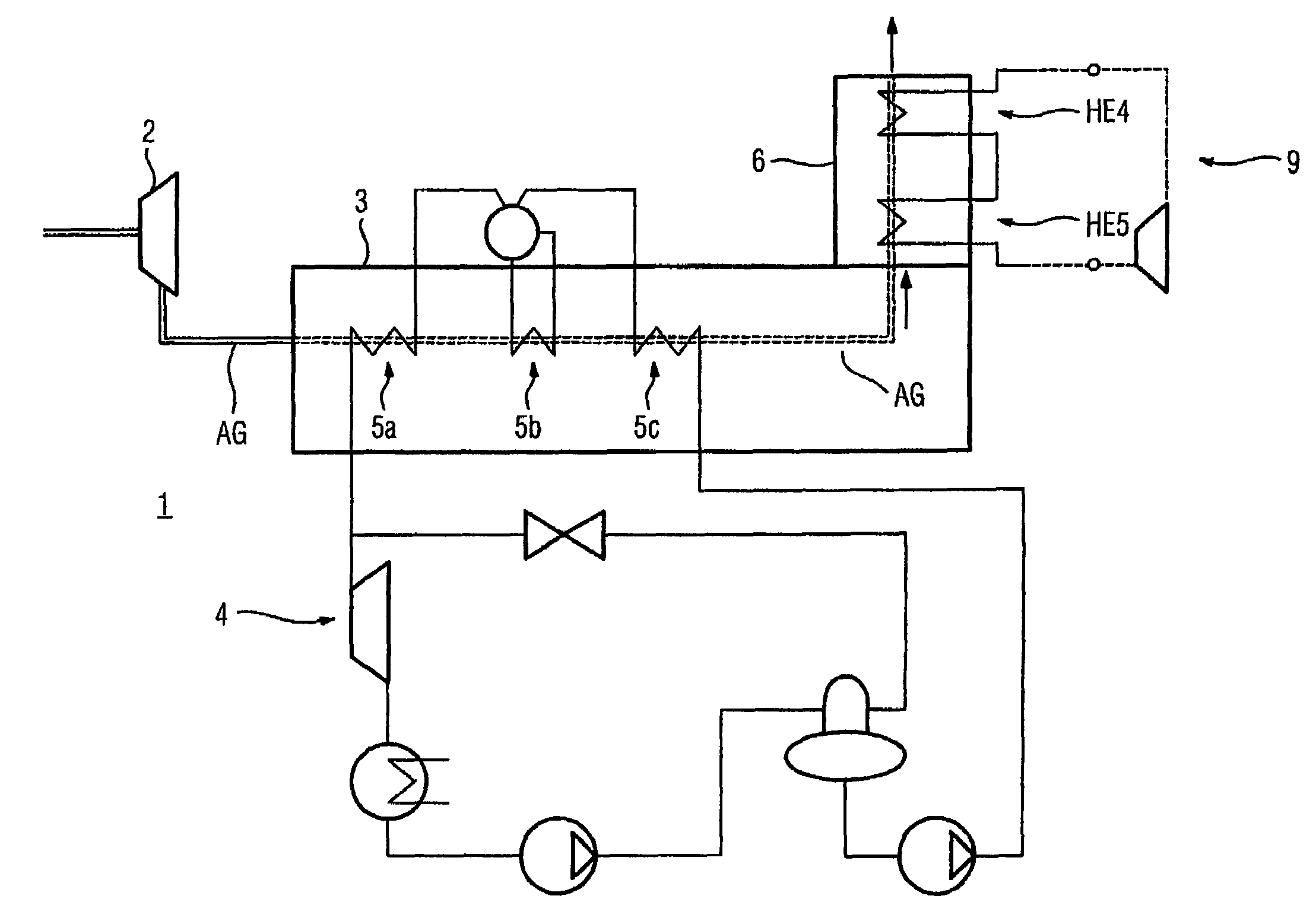
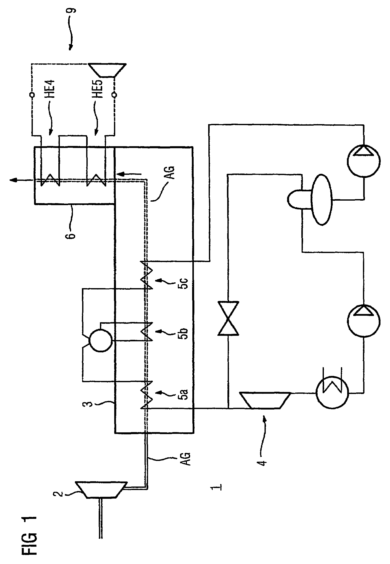
[0031]FIG. 1 shows a schematic diagram of a combined cycle gas and steam turbine system 1 with a gas turbine 2 and a waste heat vessel 3 through which the hot waste gases AG of the gas turbine 2 flow. The gas turbine is operated with an open gas turbine process.

[0032]In an outlet air chimney 6 of the combined cycle gas turbine system 1 are two heat exchangers HE4, HE5 for transmission of at least a part of the heat of the waste gases AG to a device 9 shown in simplified form for carrying out a thermodynamic circulation process with a working medium with at least two substances with non-isothermal evaporation and condensation. The thermodynamic circulation process involved is for example a Kalina cycle.

[0033]On the waste gas side three heat exchangers 5a, 5b, 5c of the water / steam circulation 4 of the combined cycle gas turbine system 1 are connected between the gas turbine and the heat exchangers HE4 and HE5. The heat exchangers 5a, 5b, 5c are arranged in the waste heat vessel 3 and...


PUM


Abstract

The aim of the invention is to increase the efficiency of a gas turbine system. Said aim is achieved by transferring at least one portion of the heat of the waste gases of a gas turbine to a working medium of a thermodynamic circulation process, which comprises at least two substances featuring non-isothermal evaporation and condensation. Said circulation process allows the residual heat of the waste gases to be used for additionally generating electrical or mechanical power, especially at waste gas temperatures ranging from 100 to 200° C. Even previously existing systems can be retrofitted in a simple manner with such a circulation process.

Description

CROSS REFERENCE TO RELATED APPLICATIONS[0001]This application is the US National Stage of International Application No. PCT / EP2004 / 007385, filed Jul. 06, 2004 and claims the benefit thereof. The International Application claims the benefits of German Patent application No. 10335143.4 filed Jul. 31, 2003. All of the applications are incorporated by reference herein in their entirety.FIELD OF THE INVENTION[0002]The invention relates to a method for increasing the efficiency of a gas turbine system in accordance with the claims as well as to a gas turbine system suitable therefor in accordance with the claims.BACKGROUND OF THE INVENTION[0003]As a result of intensive development work in recent years higher levels of efficiency, i.e. the ratio of electrical or mechanical power able to be generated in relation to the fuels used of around 40%, can be achieved with gas turbines. Combined cycle gas turbine (CCGT) systems, as are known for example from EP 0898 641 A1, make it possible to go b...

Claims


Application Information

Patent Timeline
Patent Type & Authority Patents(United States)
IPC IPC(8): F02C1/00F01K25/06F02C6/10F01K23/10
CPCF01K23/10F01K25/065Y02E20/14Y02E20/16F01K25/06
Inventor KLAUS, ROLANDLENGERT, JORGRUHSLAND, KATHRIN
Owner KALINA POWER LTD
Why Eureka
Try Eureka