Method of using sacrificial materials for fabricating internal cavities in laminated dielectric structures

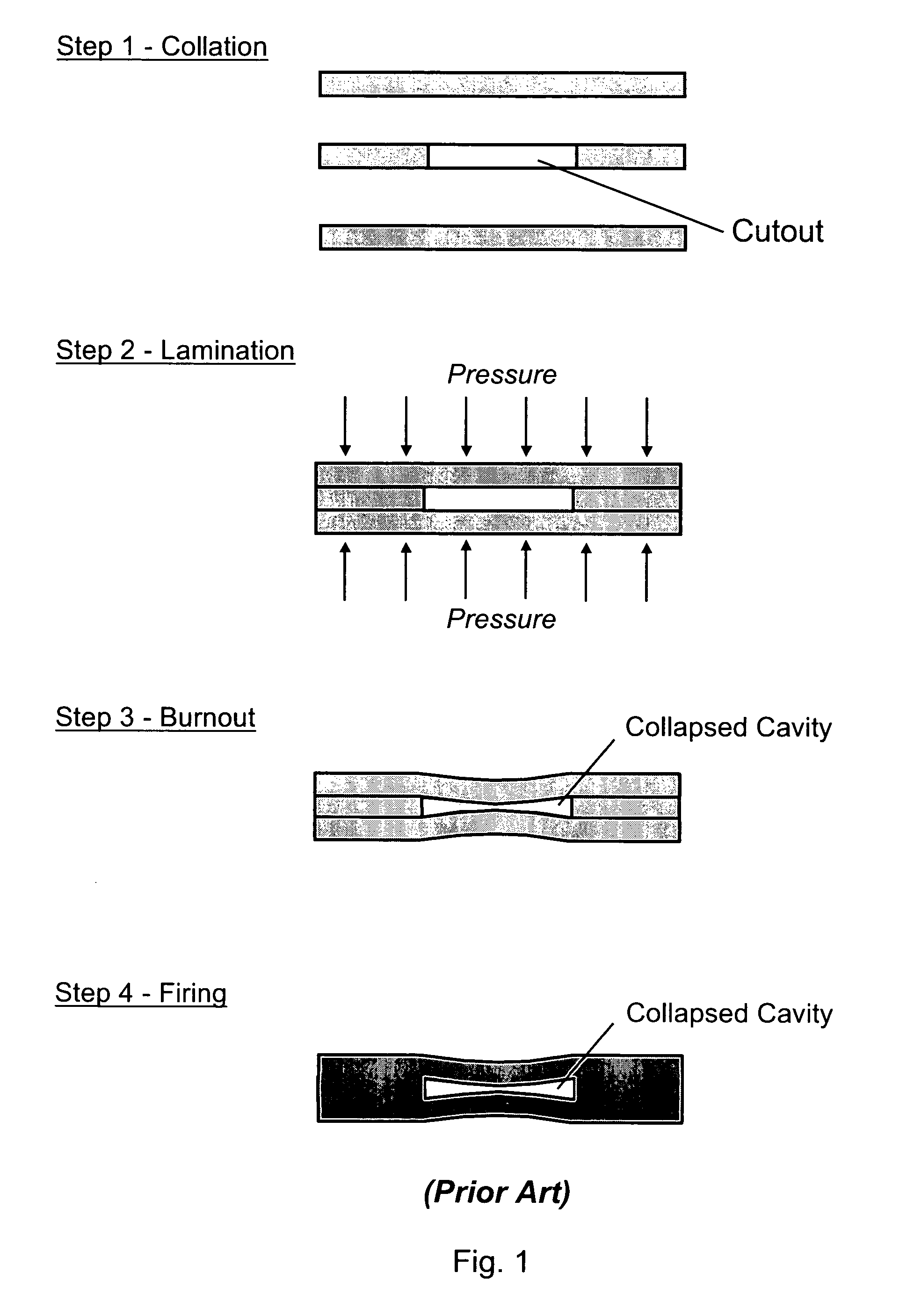
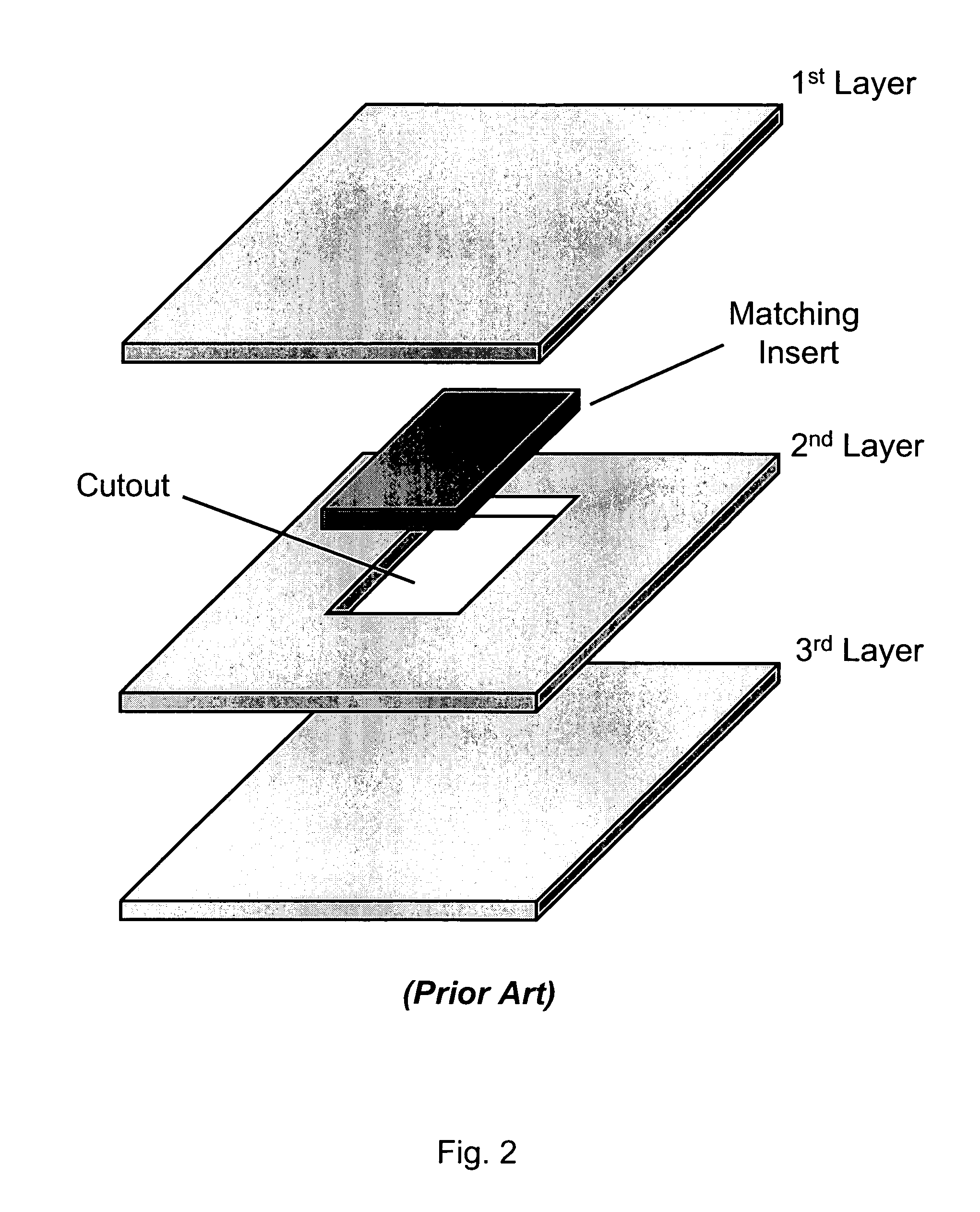
a technology of laminated dielectric structure and sacrificial materials, which is applied in the field of using sacrificial materials for fabricating internal cavities and channels in laminated dielectric structures, can solve the problems of sacrificial material burnout, internal cavity walls above and below the cutout can sag or even collapse, and all of these steps require additional time and costs

Active Publication Date: 2009-02-24
NAT TECH & ENG SOLUTIONS OF SANDIA LLC
View PDF16 Cites 68 Cited by
  • Summary
  • Abstract
  • Description
  • Claims
  • Application Information

AI Technical Summary

Benefits of technology

[0020]The present invention relates to a method of using sacrificial materials for fabricating internal cavities and channels in laminated dielectric structures, which can be used as dielectric substrates and package mounts for microelectronic and microfluidic devices. A sacrificial mandrel is placed in-between two or more sheets of a deformable dielectric material (e.g., unfired LTCC glass / ceramic dielectric), wherein the sacrificial mandrel is not inserted into a cutout made in any of the sheets. The stack of sheets is laminated together, which deforms the sheet or sheets around the sacrificial mandrel. After lamination, the mandrel is removed, (e.g., during LTCC burnout), thereby creating a hollow internal cavity in the monolithic ceramic structure.

Problems solved by technology

However, if the dimension of the cutout is much wider than it is tall, then during the lamination step the internal cavity walls above and below the cutout can sag or even collapse when high pressures are applied.
Then, the sacrificial material burns out during the burnout step.
All of these steps require additional time and costs.
When the internal cavity comprises complex-shapes or multiple-curved channels (e.g., serpentine channels), then the steps of making the cutout and fabricating a matching insert become even more expensive and time-consuming.
At some level of complexity (of the cutout pattern), the costs of using complex shaped inserts is prohibitive.

Method used


Image

  • Method of using sacrificial materials for fabricating internal cavities in laminated dielectric structures
  • Method of using sacrificial materials for fabricating internal cavities in laminated dielectric structures
  • Method of using sacrificial materials for fabricating internal cavities in laminated dielectric structures

Examples


Embodiment Construction

[0049]Hereinafter, when the term “LTCC” is used, it defined to include the HTCC material system, unless specifically stated otherwise. The term “green tape” is herein used interchangeably with “unfired ceramic”. The term “green tape” is defined to include “green sheets”. The word “cavity” is defined to include channels, microchannels, capillaries, conduits, wells, internal volumes, blind volumes, passageways, manifolds, and grooves. The terms “fugitive insert”, “sacrificial mandrel”, and “sacrificial volumes” are all used interchangeably to refer to a piece of sacrificial material that is subsequently removed from the finished structure after being used to define an internal cavity.

[0050]FIG. 4 shows an isometric view of a sacrificial mandrel disposed in-between two layers of deformable dielectric material, according to the present invention. First layer 12 and second layer 16 comprise a deformable dielectric material, which may be the same or different material. Examples of deforma...


PUM

PropertyMeasurementUnit
diameteraaaaaaaaaa
pressureaaaaaaaaaa
thicknessaaaaaaaaaa

Abstract

A method of using sacrificial materials for fabricating internal cavities and channels in laminated dielectric structures, which can be used as dielectric substrates and package mounts for microelectronic and microfluidic devices. A sacrificial mandrel is placed in-between two or more sheets of a deformable dielectric material (e.g., unfired LTCC glass/ceramic dielectric), wherein the sacrificial mandrel is not inserted into a cutout made in any of the sheets. The stack of sheets is laminated together, which deforms the sheet or sheets around the sacrificial mandrel. After lamination, the mandrel is removed, (e.g., during LTCC burnout), thereby creating a hollow internal cavity in the monolithic ceramic structure.

Description

FEDERALLY SPONSORED RESEARCH[0001]The United States Government has rights in this invention pursuant to Department of Energy Contract No. DE-AC04-94AL85000 with Sandia Corporation.CROSS-REFERENCE TO RELATED APPLICATIONS[0002]NoneBACKGROUND OF THE INVENTION[0003]The present invention relates generally to a method of using sacrificial materials for fabricating internal cavities and channels in laminated dielectric structures, which can be used as dielectric substrates and package mounts for microelectronic and microfluidic devices.[0004]Multilayered, laminated dielectric structures are commonly used in microelectronic and microfluidic devices for substrates and package mounts. Multilayered dielectric materials include printed wiring board (PWB) laminate materials, low-temperature co-fired glass / ceramic dielectric materials (LTCC) and high-temperature co-fired ceramic / glass (HTCC) materials.[0005]For storing and operating microelectronic devices in severe environments, ceramic packages...

Claims


Application Information

Patent Timeline
Patent Type & Authority Patents(United States)
IPC IPC(8): C03B29/00
CPCB32B18/00H05K1/0272H05K3/4697C04B2237/62H05K1/0306H05K3/4611H05K3/4629H05K2203/308C04B2235/5436C04B2235/6581C04B2237/363C04B2237/385C04B2235/6028
Inventor PETERSON, KENNETH A.
Owner NAT TECH & ENG SOLUTIONS OF SANDIA LLC
Why Eureka
Try Eureka