Servo writing a disk drive by writing spiral tracks using a mechanical position sensor

a technology of mechanical position sensor and disk drive, which is applied in the field of disk drives, can solve the problems of inability to accurately predict the speed of the disk drive, the calibration process will inevitably exhibit some degree of error, and the cost of external servo writers

Inactive Publication Date: 2009-02-24
WESTERN DIGITAL TECH INC
View PDF82 Cites 127 Cited by
  • Summary
  • Abstract
  • Description
  • Claims
  • Application Information

AI Technical Summary

Benefits of technology

[0015]Another embodiment of the present invention comprises a method of servo writing a disk drive, the disk drive comprising a disk, an actuator arm, a head attached to a distal end of the actuator arm, a mechanical position sensor operable to generate a position signal representing a position of the head relative to the disk, and a voice coil motor for rotating the actuator arm about a pivot. The disk is rotated at a predetermined velocity, a control signal is generated in response to the position signal generated by the mechanical position sensor, and the control signal is applied to the voice coil motor in order to seek the head radially over the disk while writing a spiral track to the disk. The spiral track is then processed to maintain the head along a servo track while writing product servo sectors along the servo track.

Problems solved by technology

However, external servo writers are expensive and require a clean room environment so that a head positioning pin can be inserted into the HDA without contaminating the disk.
Thus, external servo writers have become an expensive bottleneck in the disk drive manufacturing process.
However, the calibration process will inevitably exhibit some degree of error, and the dynamics of the disk drive will change between seeks inducing errors in the radial position of the spiral tracks.
Dynamic errors which degrade the spiral tracks written during an open loop seek include vibration of the HDA, flutter and non-repeatable run-out of the disk and spindle bearings, stiction and non-repeatable run-out of the pivot bearings, windage on the head and arm, and flex circuit bias, windage and vibration.
Errors in writing the spiral tracks will propagate to the product servo sectors, thereby degrading the operating performance of the disk drive and reducing the manufacturing yield.

Method used


Image

  • Servo writing a disk drive by writing spiral tracks using a mechanical position sensor
  • Servo writing a disk drive by writing spiral tracks using a mechanical position sensor
  • Servo writing a disk drive by writing spiral tracks using a mechanical position sensor

Examples


Embodiment Construction

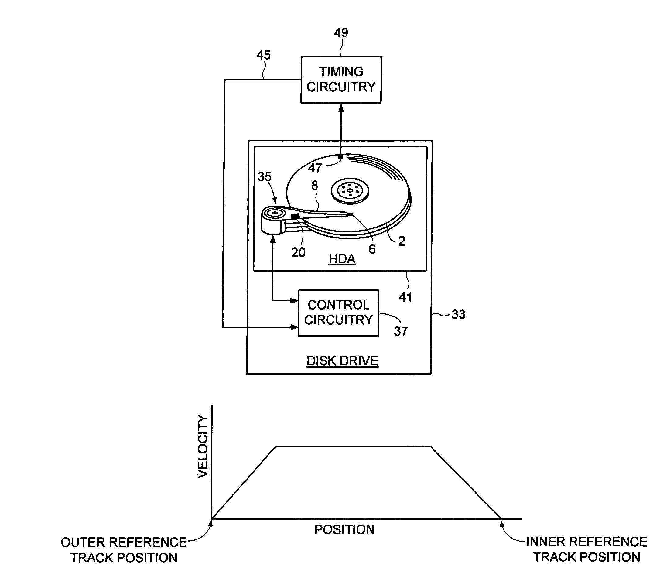
[0041]FIG. 3A shows a disk drive 33 according to an embodiment of the present invention including a disk 2, an actuator arm 8, a head 6 attached to a distal end of the actuator arm 8, a mechanical position sensor 20 operable to generate a position signal representing a position of the head 6 relative to the disk 2, and a voice coil motor 35 for rotating the actuator arm 8 about a pivot. Control circuitry 37 rotates the disk 2 at a predetermined velocity, generates a control signal in response to the position signal generated by the mechanical position sensor 20, and applies the control signal to the voice coil motor 35 in order to seek the head 6 radially over the disk 2 while writing a spiral track 39i to the disk 2 (FIG. 3C). The control circuitry 37 then processes the spiral track 39i to maintain the head 6 along a servo track while writing product servo sectors 210-21N along the servo track.

[0042]Any suitable control signal may be applied to the voice coil motor 35 in response t...


PUM

PropertyMeasurementUnit
ODaaaaaaaaaa
velocityaaaaaaaaaa
outer diameteraaaaaaaaaa

Abstract

A disk drive is disclosed including a disk, an actuator arm, a head attached to a distal end of the actuator arm, a mechanical position sensor operable to generate a position signal representing a position of the head relative to the disk, and a voice coil motor for rotating the actuator arm about a pivot. The disk is rotated at a predetermined velocity, a control signal is generated in response to the position signal generated by the mechanical position sensor, and the control signal is applied to the voice coil motor in order to seek the head radially over the disk while writing a spiral track to the disk. The spiral track is then processed to maintain the head along a servo track while writing product servo sectors along the servo track.

Description

BACKGROUND OF THE INVENTION[0001]1. Field of the Invention[0002]The present invention relates to disk drives for computer systems. More particularly, the present invention relates to servo writing a disk drive by writing spiral tracks using a mechanical position sensor.[0003]2. Description of the Prior Art[0004]FIG. 1 shows an exploded view of a prior art disk drive comprising a disk 2 rotated by a spindle motor 4, and a head 6 coupled to a distal end of an actuator arm 8 which is rotated about a pivot 10 by a voice coil motor (VCM) in order to actuate the head 6 over the disk 2. The disk 2, spindle motor 4, head 6, actuator arm 8, and VCM are enclosed in a head disk assembly (HDA) comprising a base 9 and a cover 11. The VCM comprises a voice coil 12 coupled to the base of the actuator arm 8 and one or more permanent magnets attached to a yoke 14. When the voice coil 12 is energized with current, the resulting magnetic flux interacts with the magnetic flux of the permanent magnets t...

Claims


Application Information

Patent Timeline
Patent Type & Authority Patents(United States)
IPC IPC(8): G11B21/02G11B5/596
CPCG11B5/59633G11B5/59638G11B5/59661
Inventor BENNETT, GEORGE J.
Owner WESTERN DIGITAL TECH INC
Why Eureka
Try Eureka