Control system and method for improving fuel economy

a control system and fuel economy technology, applied in the direction of electrical control, process and machine control, instruments, etc., can solve the problems of poor fuel consumption, compromise of engine fuel efficiency, software and hardware technology not being able to adjust fuel flow based on actual operating conditions, etc., to achieve maximum fuel efficiency

Inactive Publication Date: 2009-03-03
VOLVO LASTVAGNAR AB
View PDF30 Cites 69 Cited by
  • Summary
  • Abstract
  • Description
  • Claims
  • Application Information

AI Technical Summary

Benefits of technology

[0018]According to another embodiment in the present invention, a method of controlling the fuel system of a combustion engine in a vehicle is provided. The method includes a step of measuring a plurality of engine and vehicle operating conditions. Fueling parameters of the fuel system are adjusted based upon the measurements made in order to optimize the output power of the engine for maximum fuel efficiency.

Problems solved by technology

Until recently, software and hardware technology were not capable of adjusting fuel flow based upon actual operating conditions.
Engines offered in the industry are currently available optimized at either point A or point B. Point A configured engines perform best under heavy load, but poorly when lightly loaded.
Point B configured engines perform best when lightly loaded, but have poor fuel consumptions when heavily loaded.
This leads to compromises in engine fuel efficiency.
However, conditions exist where light engine loads are encountered, such as some vehicle operations under less than full cargo, at low cruising speeds, or flat or downhill road grades.
Under these conditions, fuel is wasted because the best operating point in the engine is not at the conditions the vehicle is experiencing.
The probability that an engine developed for one set of operating conditions would be mis-applied to another set of operating conditions, however, is high.

Method used


Image

  • Control system and method for improving fuel economy
  • Control system and method for improving fuel economy
  • Control system and method for improving fuel economy

Examples


Embodiment Construction

[0025]While the present invention may be embodied in many different forms, a number of illustrative embodiments are described herein with the understanding that the present disclosure is to be considered as providing examples of the principles of the invention and such examples are not intended to limit the invention to preferred embodiments described herein and / or illustrated herein.

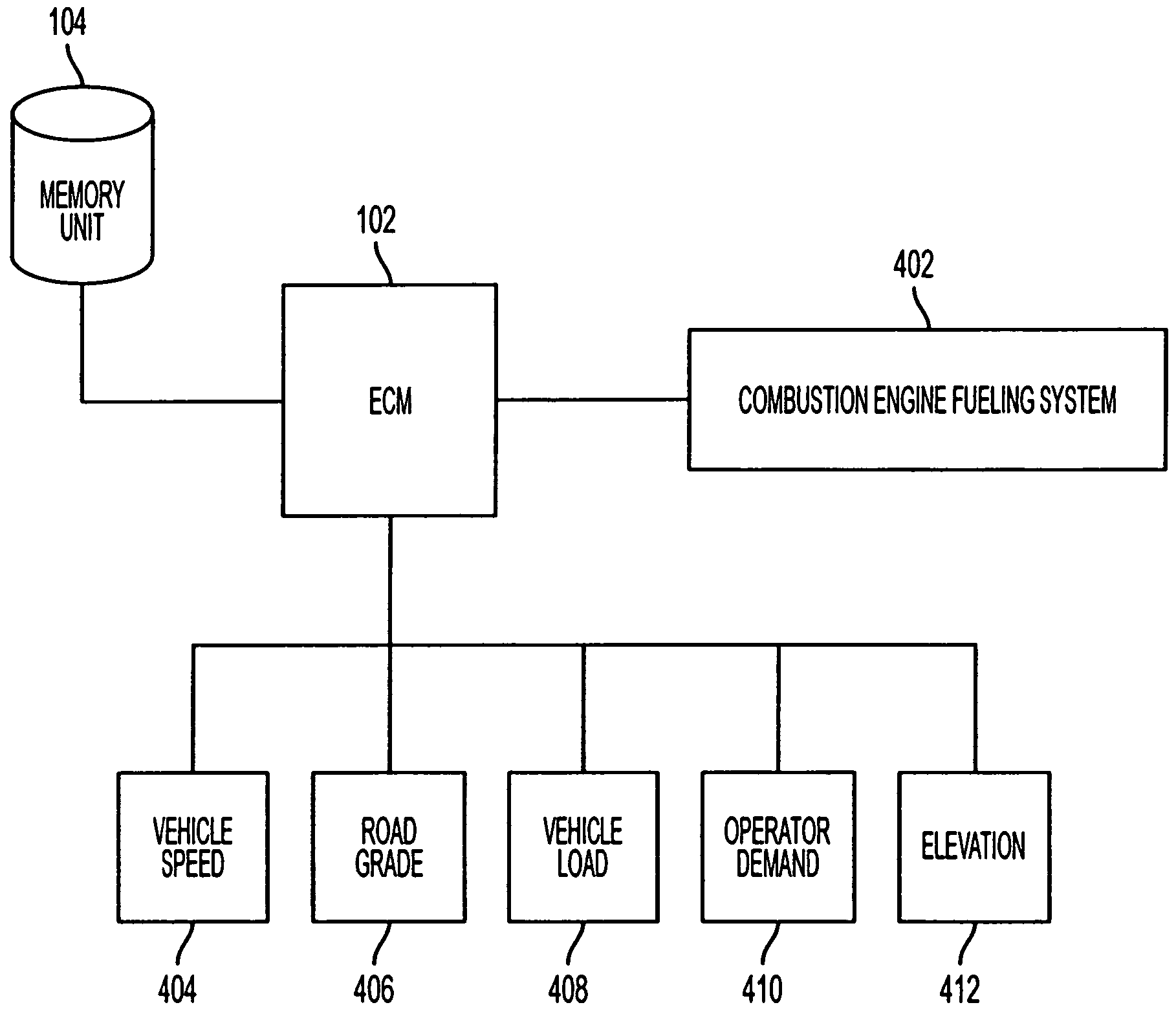
[0026]It is desirable that the performance of an engine be optimized for a variety of operating and load conditions under which it may operate. It is further desirable for the performance of an engine to be adaptable to a wide variety of road conditions under which it may operate. Finally, it is desirable for an engine to be optimizable to operate at maximum performance for all possible operating conditions. To that end, the present invention includes systems and methods for controlling a fuel system of a combustion engine, in real-time, based on engine and vehicle operating conditions.

[0027]FIG. 4 is a...


PUM


Abstract

A control system is provided for controlling the fueling system (402) of a combustion engine. The control system includes a sensing arrangement for measuring a plurality of engine and vehicle conditions (404, 406, 408, 410, 412) in real time. The control system also includes a fuel map that defines engine fueling parameters corresponding to engine operating conditions. The control system also includes a control module (102) that determines engine load from the sensed conditions, and controls the fueling parameters of the fueling system for optimized fuel consumption by selecting fueling parameters from the fuel map based on current engine load.

Description

CROSS-REFERENCE TO RELATED APPLICATIONS[0001]This application is a National Phase of International Application Ser. No. PCT / US2004 / 038217, filed 17 Nov. 2004, which claims benefit of U.S. Provisional Application Ser. No. 60 / 520,651, filed 18 Nov. 2003.BACKGROUND OF THE INVENTION[0002]1. Field of the Invention[0003]The invention relates to engine control systems, and in particular to engine control systems for controlling the fueling system in a combustion engine.[0004]2. Description of the Related Art[0005]Engine control systems for controlling fueling in combustion engines often utilize fuel maps, such as shown in FIG. 1, which define the amount of fuel to be supplied for an engine operating condition. In FIG. 1, the bold line 100a represents the rated power (i.e., brake power) of the engine, and the contoured wave lines 100b represent the amount of fuel metered per horsepower (lbs / hp / hr). The curves 100a-100b are graphed against engine speed in revolutions per minute (RPS).[0006]I...

Claims


Application Information

Patent Timeline
Patent Type & Authority Patents(United States)
IPC IPC(8): F02M7/00G06F19/00F02D41/24
CPCF02D41/2422F02D2200/501F02D2200/602F02D2200/701F02D2200/703
Inventor HOLLENBECK, BRUCE PHELPS
Owner VOLVO LASTVAGNAR AB
Why Eureka
Try Eureka