Triangular shaped heat exchanger

a heat exchanger and triangular technology, applied in the direction of domestic stoves or ranges, stationary conduit assemblies, lighting and heating apparatus, etc., can solve the problems of reducing the efficiency reducing the amount of air that passes directly through the coil, and inefficient orientation, so as to reduce the number of heat exchangers, and reduce the size of the heat exchanger

Inactive Publication Date: 2009-03-03
TRI X FLO
View PDF9 Cites 14 Cited by
  • Summary
  • Abstract
  • Description
  • Claims
  • Application Information

AI Technical Summary

Benefits of technology

[0014]A further advantage of the present invention is that the present invention has a smaller footprint and therefore takes up less room than conventional box type heat exchangers. This makes the present invention suitable for installations where space is limited.
[0015]A still further advantage is that the present invention can be designed to accommodate multiple service heat exchanger coils, thereby allowing a single heat exchanger to serve several different applications. This versatility decreases the number of heat-exchangers required for a facility, resulting in installation and operational savings.SUMMARY OF THE INVENTION
[0016]The present invention is a heat exchanger having two walls of heat exchanger coils oriented at double or compound angles with respect to a plane in which its associated heat exchanger fan is located. The bottom edge of each heat exchanger coil wall is oriented at an angle of approximately 60 degrees to the plane in which the fan operates, and each heat exchanger coil is tilted inward at an angle of approximately 60 degrees relative to a plane connecting the two bottom edges of the heat exchanger coil wall. Each of these angles can be varied by approximately 25 degrees, although it is believed that 60 degrees is the optimum orientation for each of these two angles. Thus, the bottom edge of each heat exchanger coil wall can be oriented at an angle of between approximately 35 and 85 degrees to the plane in which the fan operates, and each heat exchanger coil is tilted inward at an angle of between approximately 35 and 85 degrees relative to a plane connecting the two bottom edges of the heat exchanger coil wall. By orienting the coils in this manner relative to the fan, this triangular shaped heat exchanger operates more efficiently than conventional box type heat exchangers.
[0017]Each heat exchanger coil wall can be provided with one or with multiple coils that can provide heat exchange capability to a variety of applications. Also, an optional top heat exchanger coil can be added to the top of the heat exchanger to provide added heat exchange capacity.
[0018]The front or nose of the heat exchanger normally forms a pointed and downwardly sloping end where the two sloping front edges of the heat exchanger coil walls meet at the front of the heat exchanger. This front edge extends downward and secures to the front point of the triangular shaped base of the heat exchanger. This arrangement works well for forced draft heat exchangers where the heat exchanger fan is pushing air through the plenum and then out of the heat exchanger through the coils. However, on induced draft heat exchangers where the heat exchanger fan is pulling air through the coil, then through the plenum and finally out of the heat exchanger through the fan, the front end of the heat exchanger does not need to be pointed. For those induced draft units, the heat exchanger coil wall can be terminated at the front edge of the heat exchanger coils and a triangular shaped plate can be used to secure together the front edges of the shortened heat exchanger coil walls and the front edge of a modified base of the heat exchanger. The modified base of the induced draft unit would be trapezoidal shaped.

Problems solved by technology

This orientation is inefficient for several reasons.
First, because the air is impinging on the coil at an angle, the amount of air that passes directly through the coil is reduced, thereby reducing the efficiency of the heat exchanger.
This bounced back air causes turbulence and noise.
It also causes back pressure on the fan which further decreases the efficiency of the heat exchanger since the fan must now work harder to overcome the increased backpressure within the plenum area of the heat exchanger.
Because the fan is working harder against the increased back pressure within the plenum, the operating life of the fan will be shortened.
This recirculation of hot discharge air through the heat exchanger further decreases the operation efficiency of the conventional box type heat exchanger.
Still another problem with conventional box type heat exchangers is that they do not produce good air flow coverage in the center of the coils or in the corners of the coils.
The poor air coverage of these units results in a decrease in the life of their coils and in their associated compressors.

Method used


Image

  • Triangular shaped heat exchanger
  • Triangular shaped heat exchanger
  • Triangular shaped heat exchanger

Examples


Embodiment Construction

The Invention

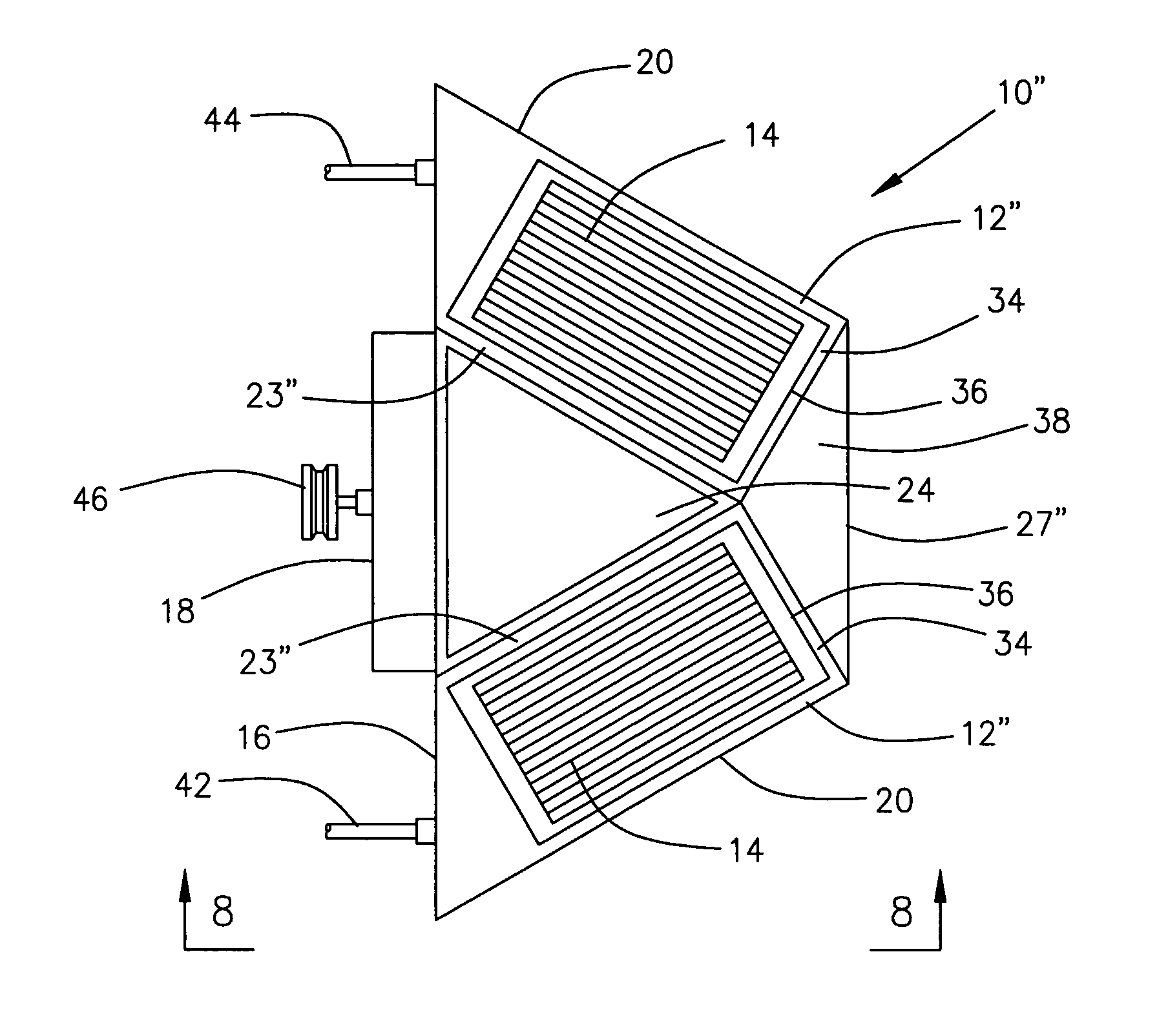
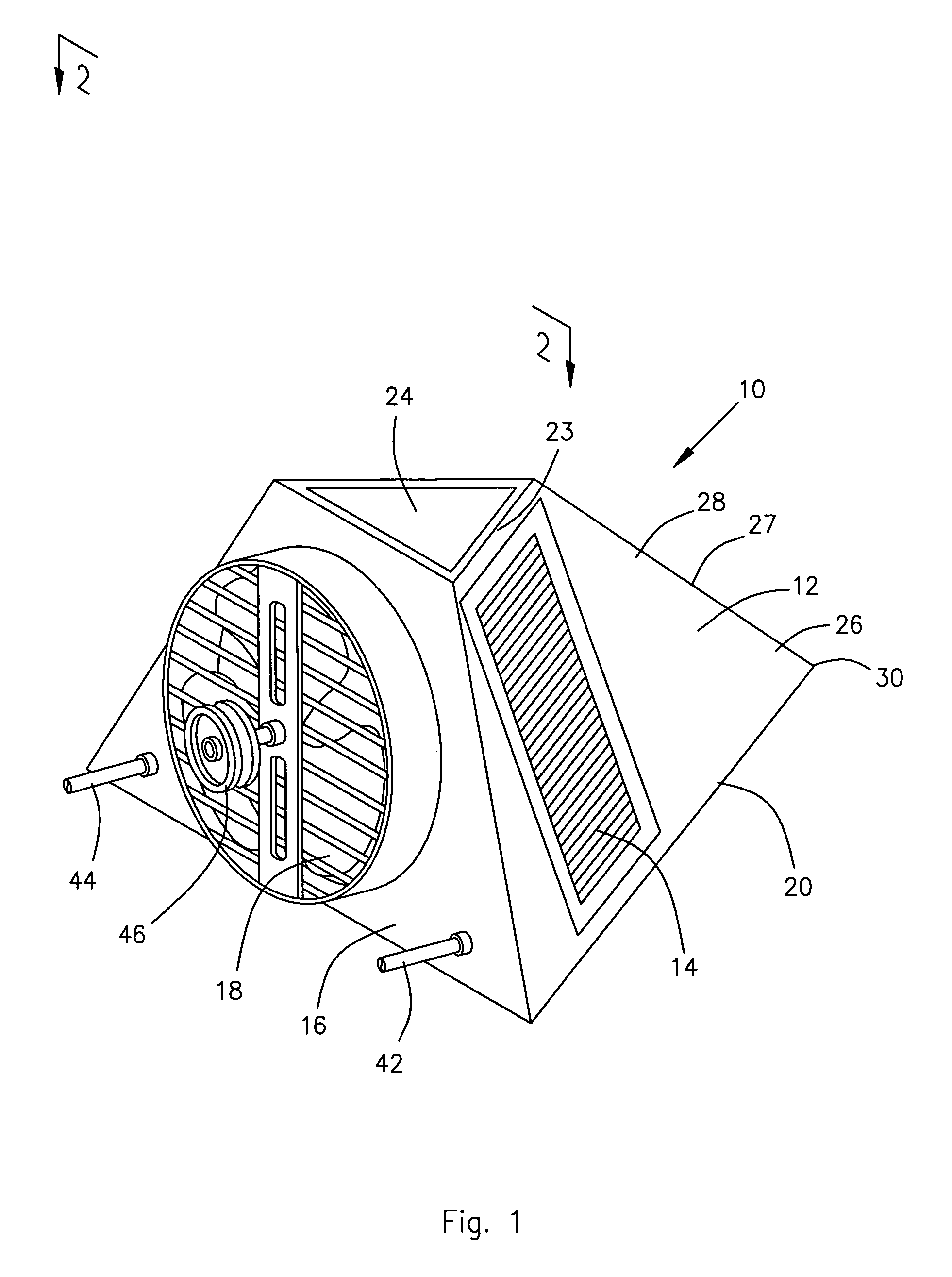
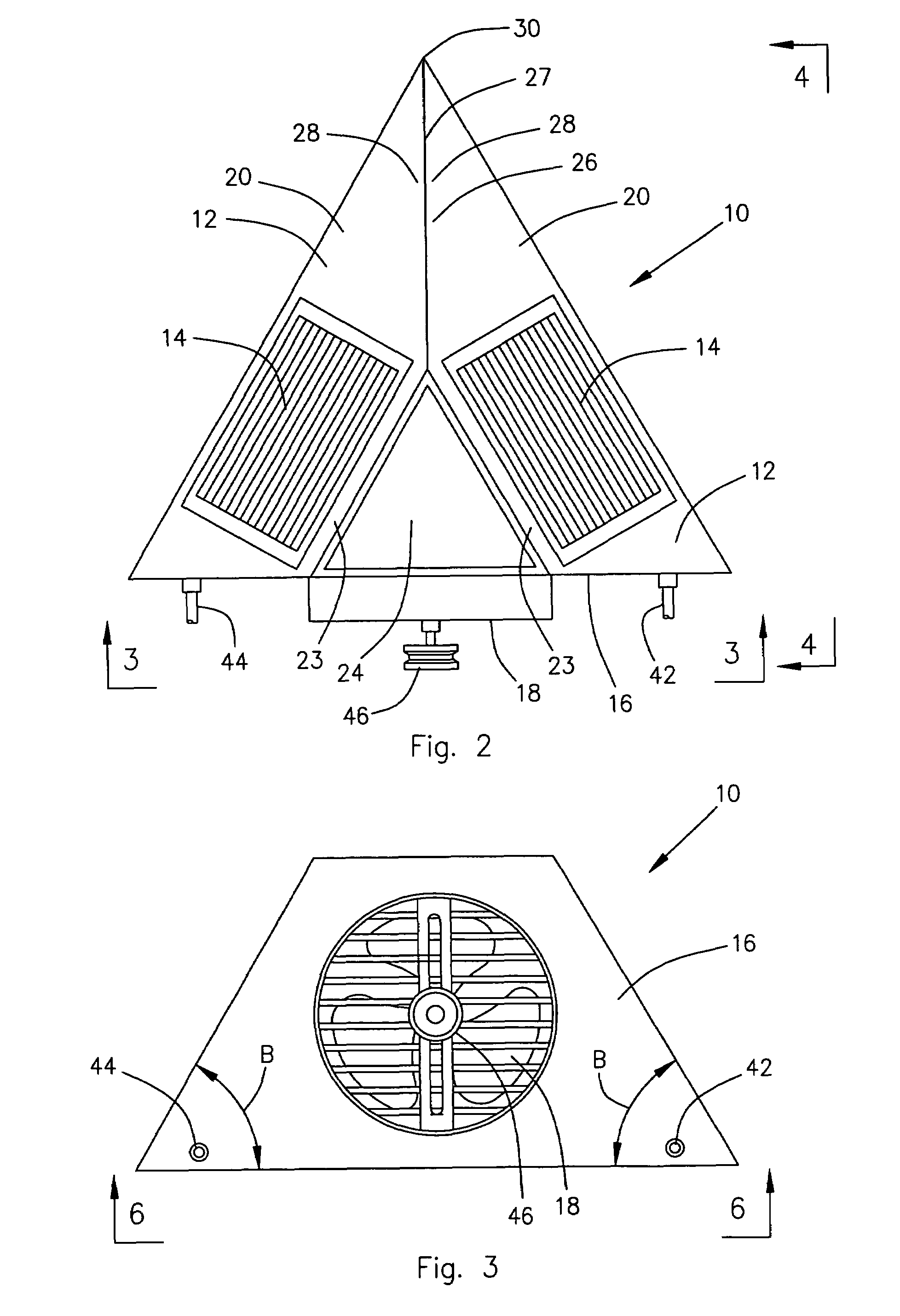
[0032]Referring now to the Figures and initially to FIGS. 1-6, there is illustrated a triangular shaped heat exchanger 10 constructed in accordance with a preferred embodiment of the present invention. The heat exchanger 10 shown in these figures has two heat exchanger walls 12 containing heat exchanger coils 14, with the walls 12 oriented at double or compound angles, angles A and B, with respect to a plane 16 in which its associated heat exchanger fan 18 is located. The plane 16 in which the heat exchanger fan 18 is located is represented in the drawings by the rear wall 16 of the heat exchanger 10 on which the fan 18 is mounted to the heat exchanger 10.

[0033]A bottom edge 20 of each heat exchanger coil wall 12 is secured to a triangular shaped base 22 and a top edge 23 of each heat exchanger coil wall 12 is secured to a triangular shaped top 24. Together the rear wall 16 and its associated fan 18, the base 22, the top 24, and the two walls 12 cooperate to define an i...


PUM


Abstract

A more efficient heat exchanger with walls of heat exchanger coils oriented at compound angles with respect to its associated heat exchanger fan. The bottom edge of each heat exchanger coil wall is oriented at an angle of between approximately 35 and 85 degrees to the fan, and each heat exchanger coil is tilted inward at an angle of between approximately 35 and 85 degrees relative to a plane connecting the two bottom edges of the heat exchanger coil wall. One or multiple coils can be provided in each heat exchanger coil wall and an optional top heat exchanger coil can be added to the top of the heat exchanger. The front of the heat exchanger, which is normally pointed for forced draft units, is replaced with a triangular shaped plate and a modified trapezoidal shaped base for induced draft units.

Description

BACKGROUND OF THE INVENTION[0001]1. Field of the Invention[0002]The present invention relates to a heat exchanger with a unique orientation of the heat exchanger coils relative to the heat exchanger fan. Specifically the heat exchanger coils of the present invention are oriented so that each heat exchanger coil makes double or compound angles with respect to the plane in which the heat exchanger fan is located. By orienting the coils in this manner relative to the fan, this triangular shaped heat exchanger operates more efficiently than conventional box type heat exchangers.[0003]2. Description of the Related Art[0004]Conventional box type heat exchangers have the heat exchanger coils located in a plane that is perpendicular to a plane in which the fan operates. This orientation is inefficient for several reasons. Air exiting the heat exchanger fan does not flow directly outward at a 90 degree angle from the fan, but instead exits the fan at an angle of approximately 30 degrees. Thu...

Claims


Application Information

Patent Timeline
Patent Type & Authority Patents(United States)
IPC IPC(8): F24H3/06F28F13/12
CPCF28B1/06F28D2001/0266
Inventor COY, RANDALL L.SUMTER, JR., JOE E.
Owner TRI X FLO
Why Eureka
Try Eureka