Particle control screen with depth filtration

a technology of particle control and depth filtration, which is applied in the direction of drinking water installation, wellbore/well accessories, etc., can solve the problems of heavy oil being difficult to remove from the formation, heavy oil being generally also difficult to filter than conventional oil deposits, and reducing the life of the filter. , to achieve the effect of preventing particle build-up, increasing the particle-holding capacity of the filter, and prolonging the li

Active Publication Date: 2009-03-03
PUROLATOR FACET INC
View PDF31 Cites 23 Cited by
  • Summary
  • Abstract
  • Description
  • Claims
  • Application Information

AI Technical Summary

Benefits of technology

[0008]In various aspects, the present invention uses depth filtration to trap different size particles at different locations through out the thickness of the filtration media. Larger particles are trapped on the outer layer of mesh with the subsequent layers trapping smaller and smaller particles until reaching the final desired micron rating. This prevents particle build-up from becoming so fine that plugging occurs and increases the particles-holding capacity of the filter, which gives the filter a longer life.

Problems solved by technology

The presence of sand and other fine particles in the production fluid and well equipment often leads to the rapid erosion of expensive well machinery and hardware.
One difficulty with surface filtration is that as larger particles are captured on the filter layer, the open spaces become smaller and smaller, thus capturing smaller and smaller particles.
Eventually the particles being captured are so fine that the filter becomes plugged, severely reducing or stopping flow of formation fluids through the screen to the base pipe.
Heavy oil is more difficult to remove from the formation and also includes more particulate matter than conventional oil deposits.
Thus, heavy oil is generally also harder to filter than conventional oil deposits.

Method used


Image

  • Particle control screen with depth filtration
  • Particle control screen with depth filtration
  • Particle control screen with depth filtration

Examples


example 1

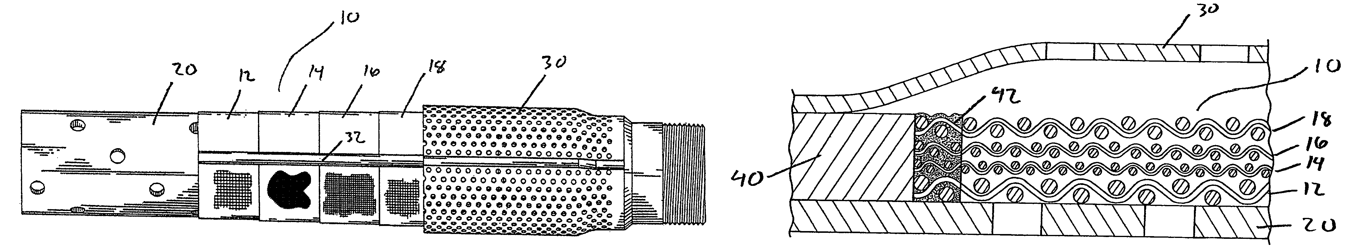
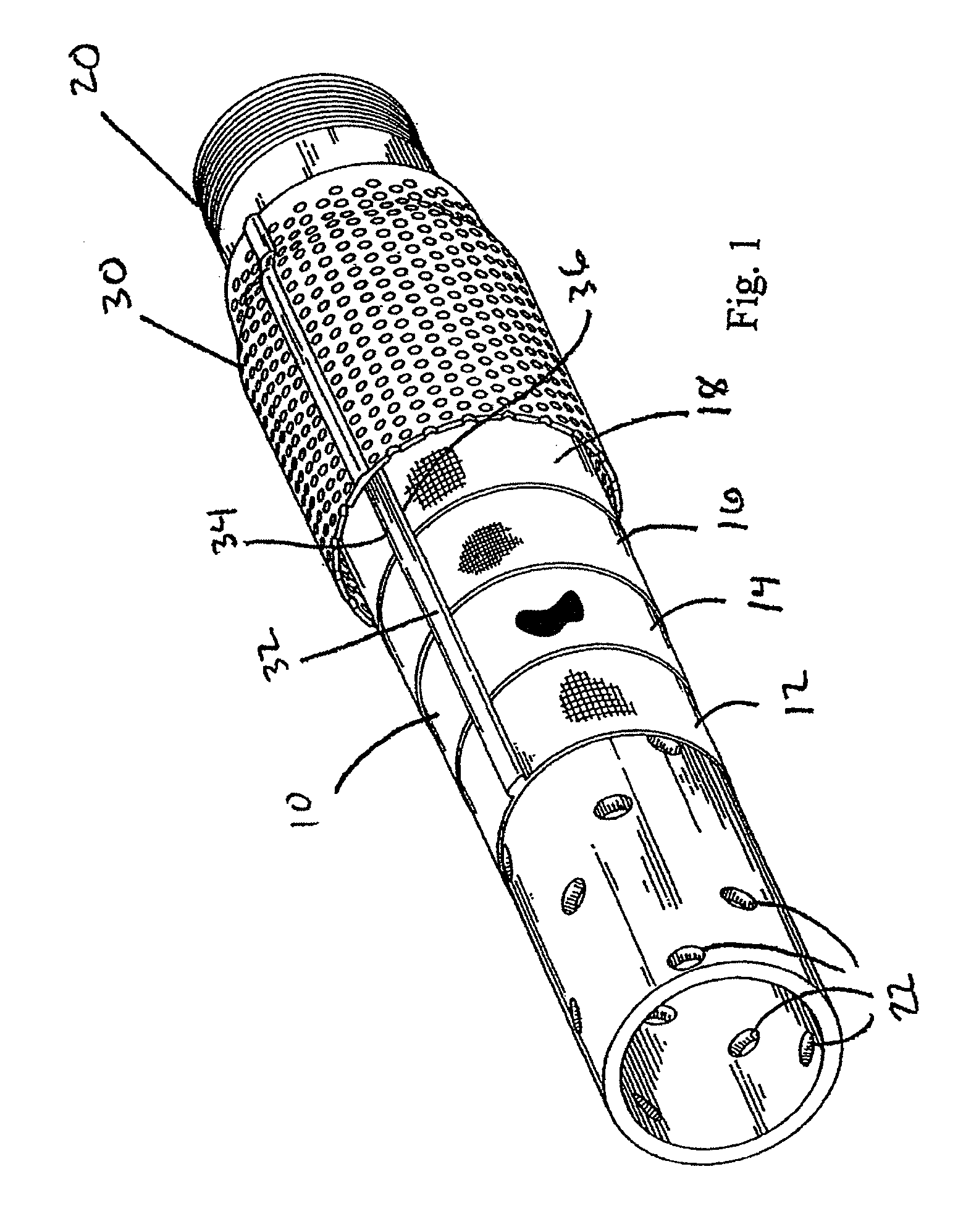
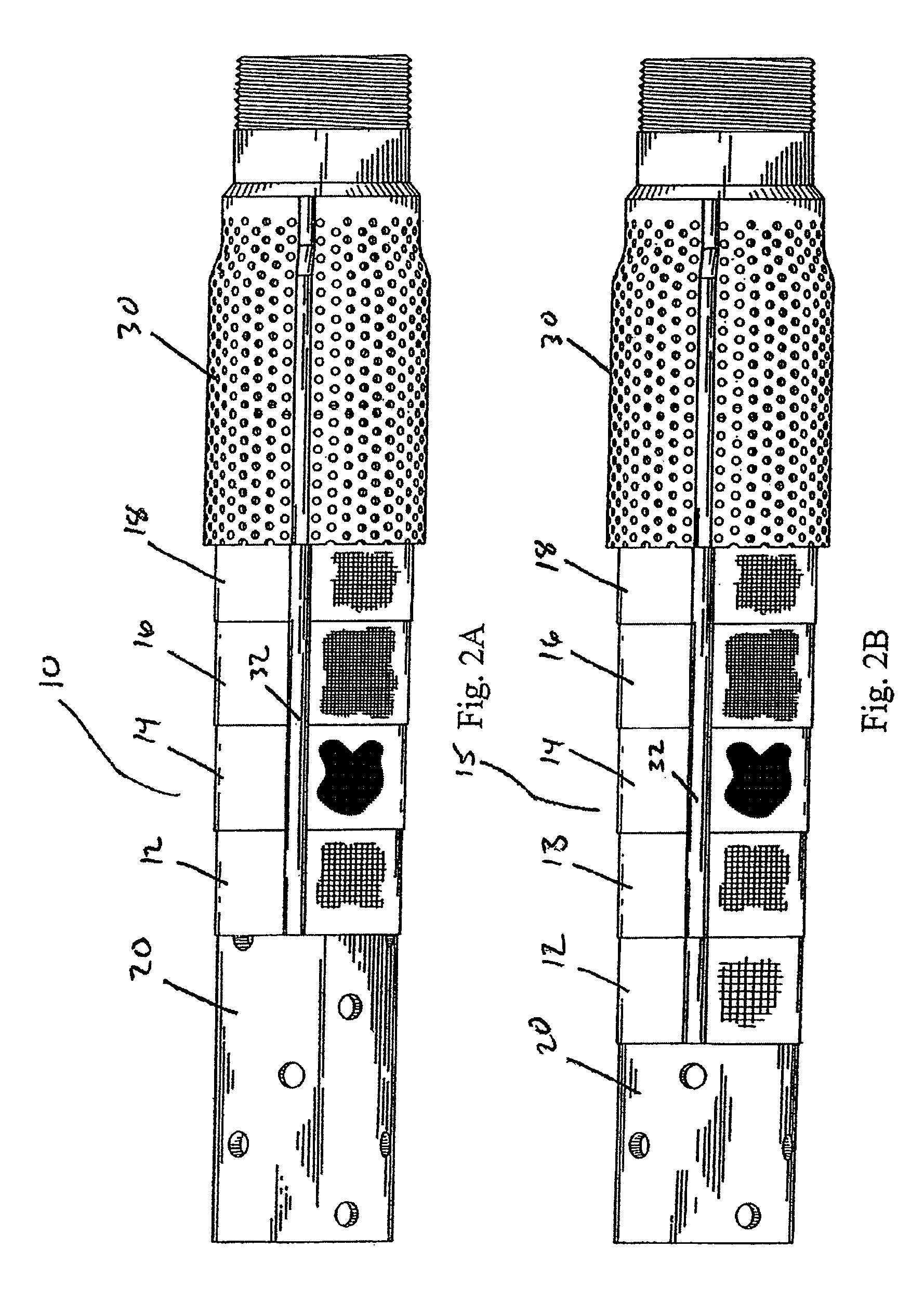
[0049]A screen assembly is prepared with a desired filtration micron rating of 125 micron. The screen assembly includes two support layers and four filter layers, as shown in Table 1 below.

[0050]

TABLE 1LayerMesh sizePore sizeOuter filter30 × 30 × 0.012540 micronIntermediate filter50 × 50 × 0.009280 micronIntermediate filter80 × 80 × 0.0055180 micronInner filter24 × 110125 micronOuter support layer20 × 20 × 0.016Inner support layer16 × 16 × 0.023

example 2

[0051]A screen assembly is prepared with a desired filtration micron rating of 180 micron. The screen assembly includes two support layers and three filter layers, as shown in Table 2 below.

[0052]

TABLE 2LayerMesh sizePore sizeOuter filter30 × 30 × 0.012540 micronIntermediate filter50 × 50 × 0.009280 micronInner filter80 × 80 × 0.0055180 micronOuter support layer20 × 20 × 0.016Inner support layer16 × 16 × 0.023

example 3

[0053]A screen assembly is prepared with a desired filtration micron rating of 250 micron. The screen assembly includes one support layer and three filter layers, as shown in Table 3 below.

[0054]

TABLE 3LayerMesh sizePore sizeOuter filter24 × 24 × 0.014700 micronIntermediate filter40 × 40 × 0.010380 micronInner filter12 × 95250 micronSupport layer16 × 16 × 0.023


PUM


Abstract

A particle control screen includes a support layer. A first filter layer is disposed around the support layer. A second filter layer is disposed around the first filter layer. A third filter layer is disposed around the second filter layer. Each of the filter layers has a pore size. The pore size of the third filter layer is greater than the pore size of the second filter layer. The pore size of the second filter layer is greater than the pore size of the first filter layer.

Description

RELATED APPLICATIONS[0001]This application claims the benefit of U.S. Provisional Patent Application No. 60 / 797,897, filed May 4, 2006, the entire disclosure of which is hereby incorporated herein by reference.BACKGROUND[0002]The present invention relates to a particle control screen for depth filtration, particularly for use in a well.[0003]Liquids and gases in oil and gas wells typically include particulates that need to be filtered, including sand, clay, and other unconsolidated particulate matter. The presence of sand and other fine particles in the production fluid and well equipment often leads to the rapid erosion of expensive well machinery and hardware.[0004]Subterranean filters, also known as sand screens or well screens, have been used in the petroleum industry to remove particulates from production fluids. The well screens are generally tubular in shape and include a perforated base pipe, a porous filter layer wrapped around and secured to the pipe, and an outer cover. T...

Claims


Application Information

Patent Timeline
Patent Type & Authority Patents(United States)
IPC IPC(8): E21B43/08E21B43/02
CPCE21B43/082
Inventor HOPKINS, SAM A.WELLS, DONALD G.
Owner PUROLATOR FACET INC
Why Eureka
Try Eureka