Electronic poll register system for elections

a register system and electronic technology, applied in the field of electronic poll register system for elections, can solve the problems of low quality, laborious process, and laborious registration totals of registered voters, and achieve the effect of low quality

Active Publication Date: 2009-03-03
WATSON DAVID
View PDF7 Cites 14 Cited by
  • Summary
  • Abstract
  • Description
  • Claims
  • Application Information

AI Technical Summary

Benefits of technology

[0009]The present invention comprises a new system for electronic polling. The system allows real-time verification of voter eligibility status with respect to voting during the designated period before and during Election Day, preventing attempts to vote more than once. The system design requires very low quality data communication lines, and will allow eligible voters to check in and be allowed to vote, even when network availability is intermittent or unavailable.
[0010]The system employs a plurality of voter check-in stations which display voter identity information and enable poll workers to verify voting eligibility. Each check-in station is connected to the internet by any available means. Periodically, the check-in station sends a block of information to a web site. The block of information includes a list of the registration numbers of all of the voters who have voted and the last time-stamp of information that it has updated onto the local database. The web site responds with a block of information containing a list of voters who have been reported as voting in other areas of the jurisdiction also a list of voters whose status has changed. The check-in station uses this information to update the local database with the voting status and eligibility status of the voters on its database. The voter check-in process runs only against the local database thereby eliminating the reliance on communications with the web site.

Problems solved by technology

Election polling officials utilize various registry systems in an effort to prevent fraudulent voting behaviors such as “double voting” and “identity fraud.” Conventional registry systems, however, are limited in a variety of ways.
This process is very labor intensive.
Obtaining an accurate cross check between tabulation totals from voting machines and totals of those who have signed the register is labor intensive, uncertain and time consuming.
Furthermore, these systems are especially vulnerable to human error since they are heavily managed by people.
For example, occasionally polling operators inadvertently fail to mark an individual's name from the list after the individual has voted or when the voter checks in at the poll.
Also, a polling operator may inadvertently mark the wrong individual's name from the list.
This mistake could cause an individual to lose his or her opportunity to vote.
This process is similarly vulnerable to human error.
Efforts to “computerize” the process, such as using a central database system, have presented different challenges.
For example, the use of a conventional central database system is vulnerable to network availability.
Disruption of the network could create serious upheaval since the remote terminal could not validate whether an individual is authorized to vote.
Another problem with computerizing the process is that some jurisdictions lack the infrastructure to provide some precincts with the high quality data communication lines necessary to maintain real-time communications with a central database without causing excessive delays in validating a voter's authorization status.
This makes the use of a computerized system less desirable because it increases the amount of time it takes for an individual to vote and causes increased waiting lines at the polls.

Method used


Image

  • Electronic poll register system for elections
  • Electronic poll register system for elections
  • Electronic poll register system for elections

Examples


Embodiment Construction

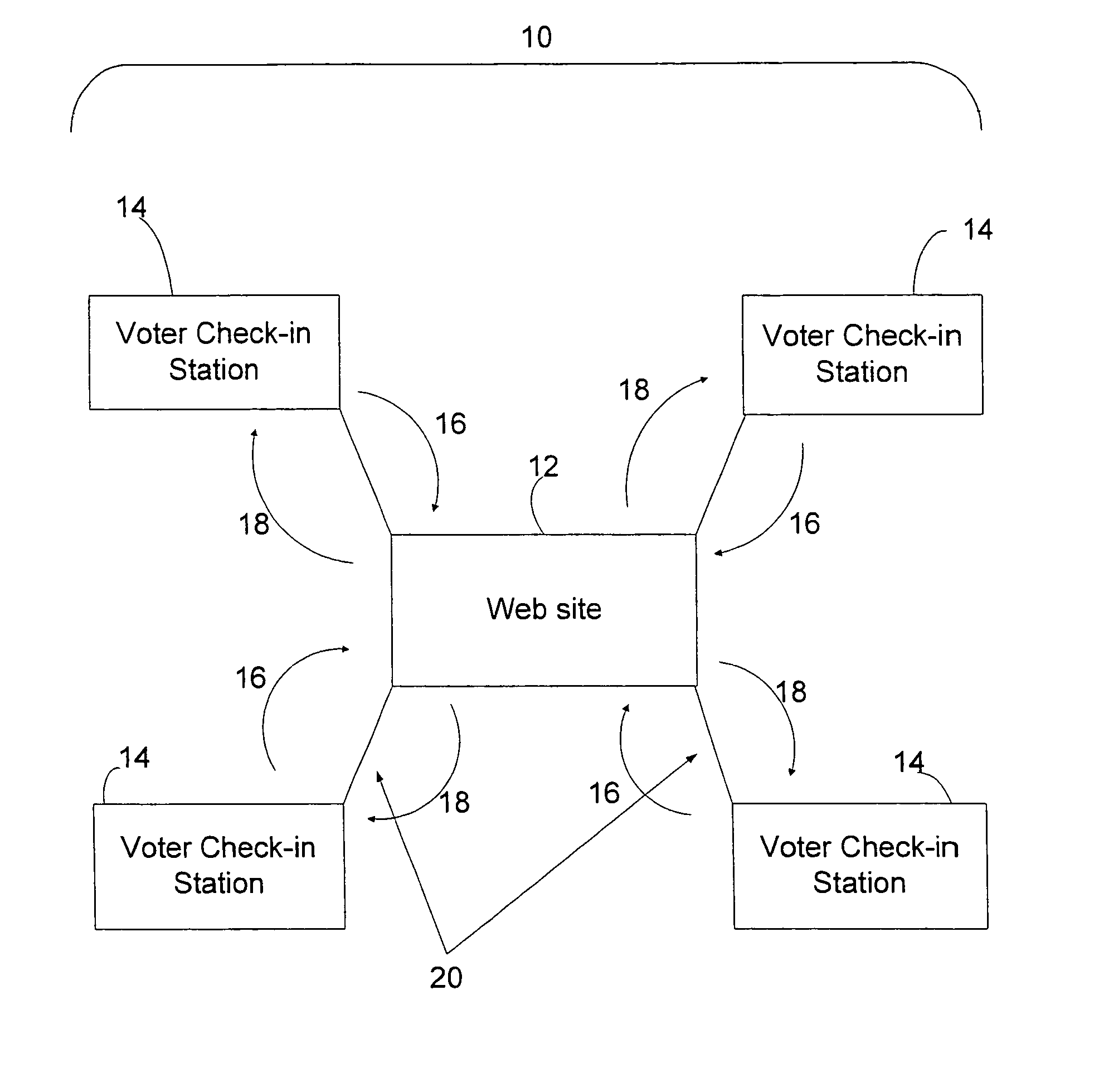
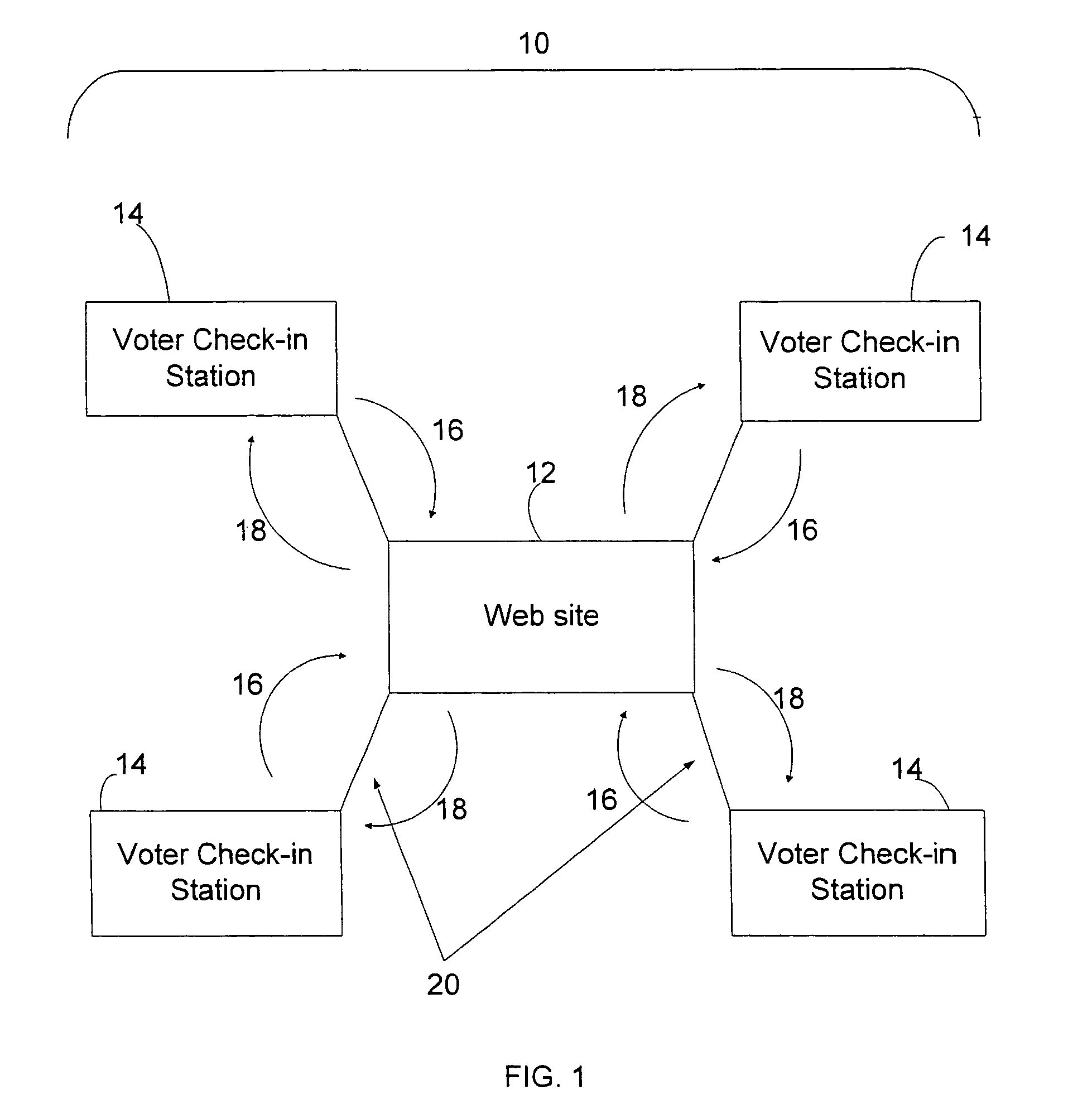
[0027]A basic configuration for a preferred embodiment of the present invention, an electronic poll register system, is shown in FIG. 1. Electronic poll register system 10 principally comprises multiple voter check-in stations 14 which are configured for connection to web site 12 by connection means 20. Conceptually, FIG. 1 can represent an electronic poll register system for a single jurisdiction with multiple polling locations, represented by voter check-in stations 14. Accordingly, FIG. 1 could represent a jurisdiction that has four polling locations.

[0028]Voter check-in station 14 is a microcomputer that is designed to display voter identity information and enable a poll worker to verify voting eligibility as quickly as possible. It holds in its local database a list of all the voters that are eligible to vote at the voting location, and also carries a list of all voters that are eligible to vote in the jurisdiction served by the voter check-in station. Examples of voter identit...


PUM


Abstract

A new system for electronic polling. The system employs a plurality of voter check-in stations which display voter identity information and enable poll workers to verify voting eligibility. Each check-in station is connected to the internet by any available means. Periodically, the check-in station sends a block of information to a web site. The block of information includes a list of the registration numbers of all of the voters who have voted and the last time-stamp of information that it has updated onto the local database. The web site responds with a block of information containing a list of voters who have been reported as voting in other areas of the jurisdiction also a list of voters whose status has changed. The check-in station uses this information to update the local database with the voting status and eligibility status of the voters on its database. The voter check-in process runs only against the local database thereby eliminating the reliance on communications with the web site.

Description

FIELD OF THE INVENTION[0001]This invention relates to the field of election polling. More specifically, the invention comprises a method and system for providing voter identity information, recording voter check-in status, and updating a central database system.DESCRIPTION OF THE RELATED ART[0002]Election polling officials utilize various registry systems in an effort to prevent fraudulent voting behaviors such as “double voting” and “identity fraud.” Conventional registry systems, however, are limited in a variety of ways. The registry systems used in many jurisdictions is nothing more than a list of names of individuals who are eligible to vote in a given precinct. In these jurisdictions, an individual is required to produce at least one of the acceptable forms of identification at the individual's designated precinct, and the individual's name is subsequently marked off of the list. These registry systems require the voter to vote only in their precinct and not from other polling...

Claims


Application Information

Patent Timeline
Patent Type & Authority Patents(United States)
IPC IPC(8): G06K17/00
CPCG07C13/00
Inventor WATSON, DAVID
Owner WATSON DAVID
Why Eureka
Try Eureka