Kinetic microplate with temporary seals

a microplate and temporary seal technology, applied in the field of multi-well sample trays, can solve the problems of evaporation loss, spillage, leakage, etc., and achieve the effect of reducing the risk of contamination, avoiding contamination, and avoiding contamination

Active Publication Date: 2009-03-03
THERMO FISHER SCI ASHEVILLE
View PDF9 Cites 6 Cited by
  • Summary
  • Abstract
  • Description
  • Claims
  • Application Information

AI Technical Summary

Benefits of technology

[0007]The foregoing needs are met, to a great extent, by the present invention, wherein in one aspect an apparatus is provided that in some embodiments a method and apparatus that delivers reagents or other materials to each individual well or to multiple wells simultaneously and efficiently.

Problems solved by technology

Such integration efforts, however, have had only limited success.
Specifically, spillage, leakage, evaporation loss, airborne contamination and inter-well cross contamination of liquid samples are some of the common deficiencies that limit the application of many standard microplate assemblies in high-throughput systems.
Consequently, one of the most critical problems confronting designers of microplate apparatus has been finding techniques of preventing the loss and contamination of well contents without unduly complicating the structures and / or handling requirements of a microplate assembly.
Some automation devices take some time to add reagents and this could be problematic for an assay requiring all reactions to take place at the same time.
Shipping compounds as solids rather than liquids, however, creates problems in dissolution that can complicate and inhibit subsequent sample evaluation procedures.
Further, an unstable solid material may disperse on opening of a closed well prior to re-dissolution.

Method used


Image

  • Kinetic microplate with temporary seals
  • Kinetic microplate with temporary seals
  • Kinetic microplate with temporary seals

Examples


Embodiment Construction

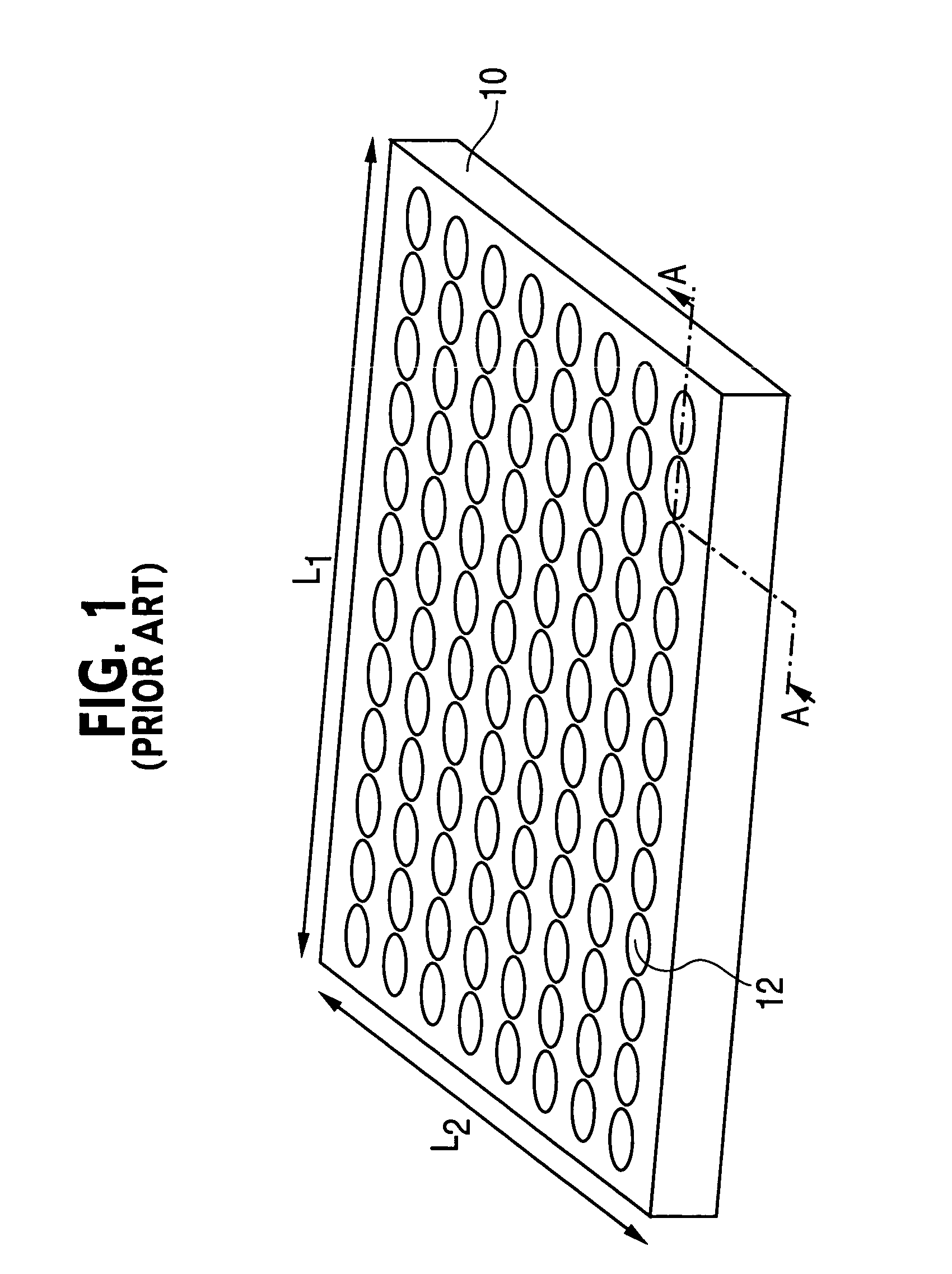
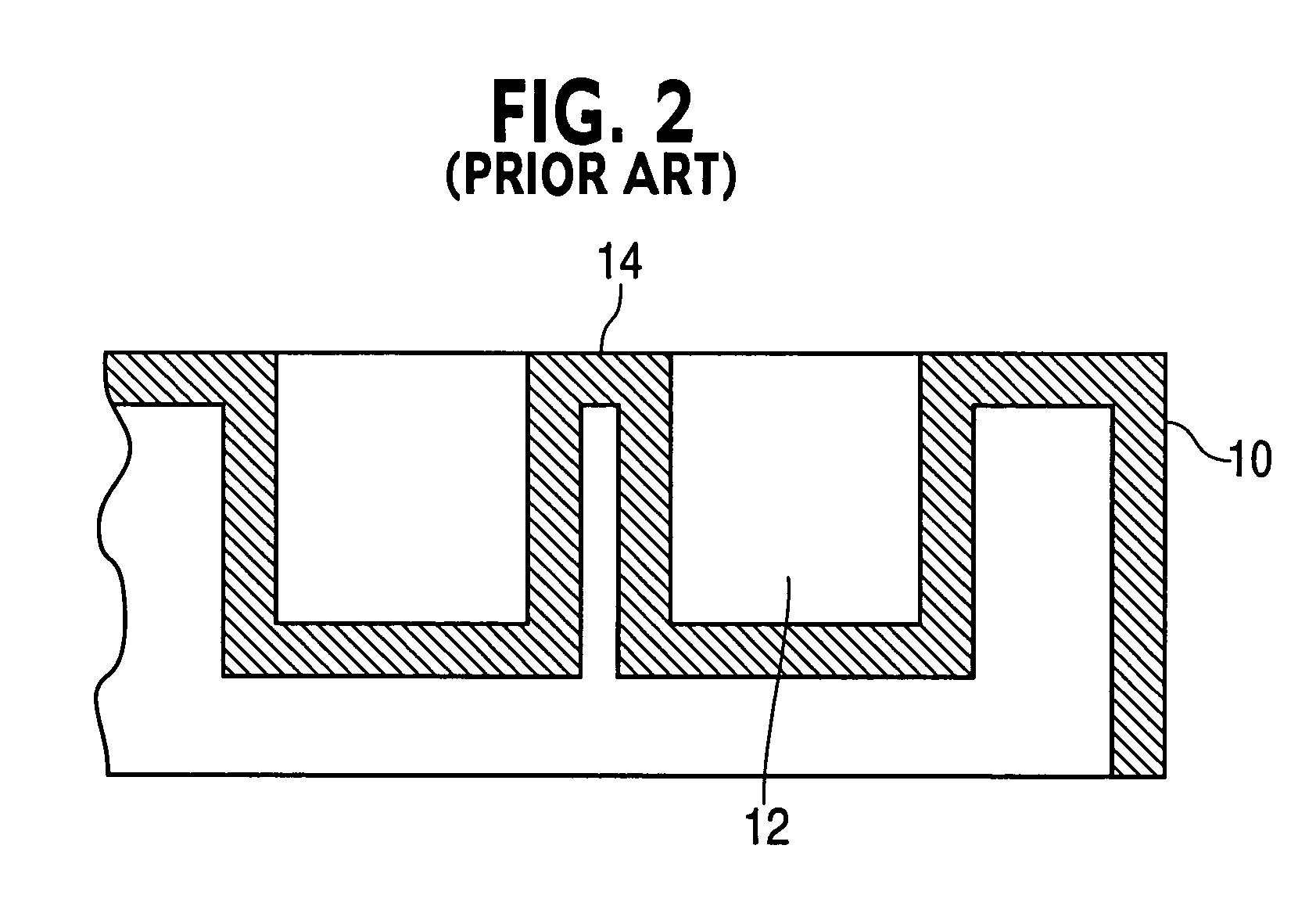
[0020]Referring to FIGS. 1-3, conventional microplates 10 may have ninety-six wells 12 arranged in an eight by twelve grid and may be composed of plastic materials such as polystyrene. Since the wells 12 are typically circular there exists area in the corners of the interstitial spaces 14 between the patterns of circular wells 12 that could be used for placement of liquids used to mix with well 12 contents.

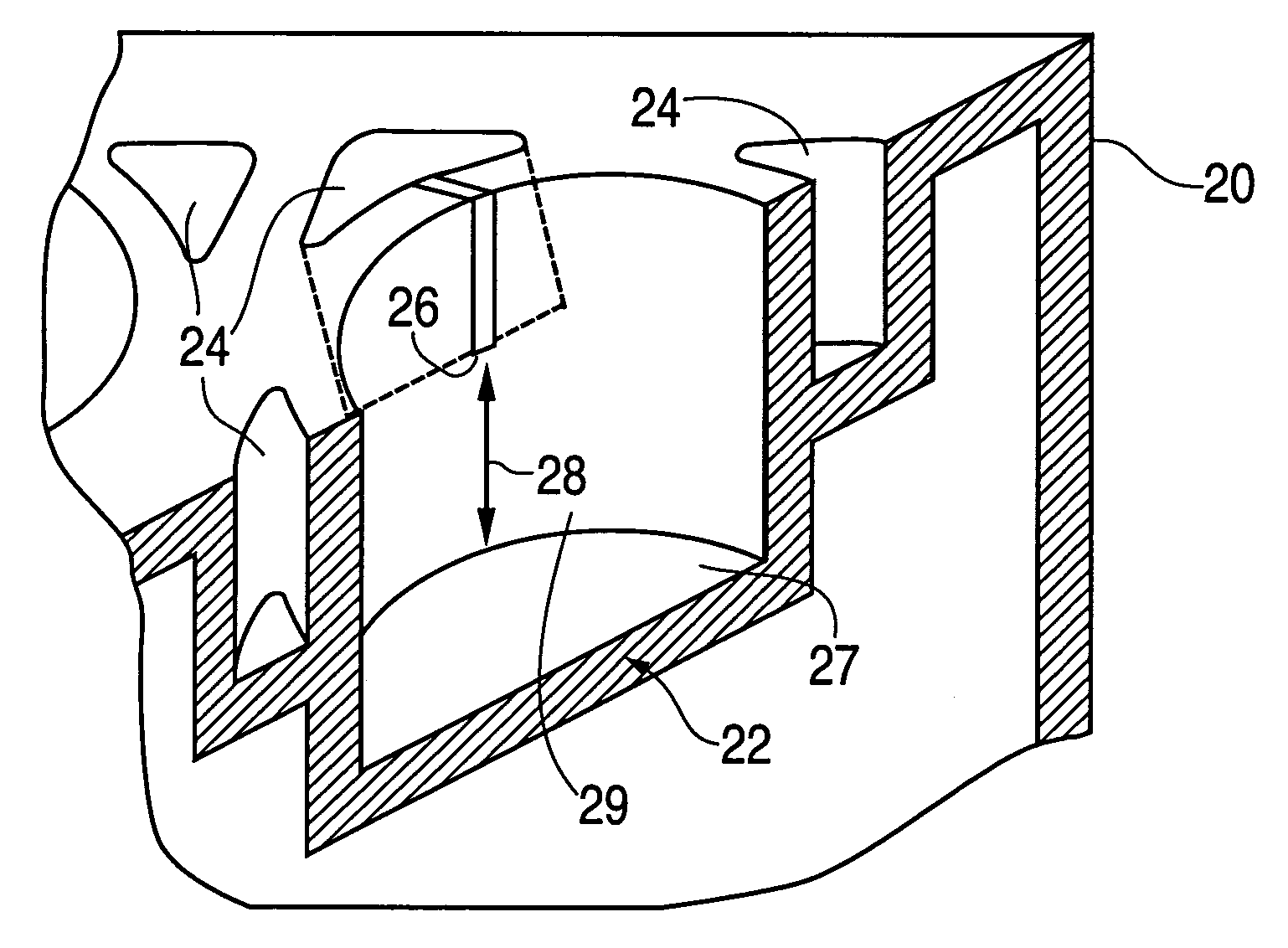
[0021]The invention will now be described with reference to the drawing figures, in which like reference numerals refer to like parts throughout. Referring to FIG. 4, an embodiment in accordance with the present invention provides a microplate 20 with corners areas 14 (shown in FIG. 3) created by the array of circular wells 22 where additional triangular-shaped sectors or wells 24 may be made to hold the kinetic or other reagents. Additionally, these wells or sectors 24 may contain temporary seals 26 so that under centrifugation all the reagent material breaks through or penetrate...


PUM

PropertyMeasurementUnit
depthaaaaaaaaaa
g-forceaaaaaaaaaa
thicknessaaaaaaaaaa

Abstract

A microplate assembly comprising a multi-well microplate and a plurality of reagent wells proximal the multi-wells. The microplate includes a frame that houses a plurality of open wells in a rectangular array. Reagent wells mounted within the microplate to react with the contents of the open wells during a g-force acting upon the microplate. The open wells function as a vessel for liquid samples that occupy predetermined spaces within the interior volumes. Each liquid sample remains within its predetermined space for all orientations of the microplate assembly.

Description

FIELD OF THE INVENTION[0001]The present invention relates generally to multi-well sample trays which are commonly referred to as microplates and which are used to hold a large number (e.g., 24, 48, 96, or more) of samples in a standardized format to be assayed by various techniques such as autoradiography, liquid scintillation counting (LSC), luminometry, etc. In particular, the present invention relates to a microplate assembly and method which permits a more efficient use of space by adding reagent wells adjacent to the multi-wells.BACKGROUND OF THE INVENTION[0002]Multi-well microplates play an important role in conventional chemical, biological, pharmacological and related processes that are designed to analyze and / or synthesize large numbers of small fluid samples. Such conventional processes normally employ multi-well microplates as tools when processing, shipping and storing the small liquid samples. Many of these processes achieve high-throughputs by applying modern automatio...

Claims


Application Information

Patent Timeline
Patent Type & Authority Patents(United States)
IPC IPC(8): G01N1/18B01L3/00
CPCB01L3/5025B01L3/5085B01L2200/16Y10T436/23B01L2400/0409Y10T436/25375B01L2300/0829
Inventor TANSEY, III, HUGH H.
Owner THERMO FISHER SCI ASHEVILLE
Why Eureka
Try Eureka