Mechanical vibration to electrical energy converter

a technology of electrical energy converter and mechanical vibration, which is applied in the direction of dynamo-electric components, dynamo-electric machines, electrical apparatus, etc., can solve the problems of energy densities and lifetimes still being issues for many systems, and the battery may have been depleted already,

Active Publication Date: 2009-03-03
NAT TECH & ENG SOLUTIONS OF SANDIA LLC
View PDF34 Cites 79 Cited by
  • Summary
  • Abstract
  • Description
  • Claims
  • Application Information

AI Technical Summary

Problems solved by technology

As wireless computing and distributed sensor networks become more mature and widespread, a bottleneck for the technology deployment becomes the power source.
Though battery technologies have improved, energy densities and lifetimes are still issues for many systems.
For many remote systems, recharging a battery is not an option.
If a system is required to remain idle for months or years and then spring to life at a certain moment, a battery may have been depleted already due to leakage or self-discharge.
Finally, batteries often involve chemicals which are harmful to humans and to the environment.

Method used


Image

  • Mechanical vibration to electrical energy converter
  • Mechanical vibration to electrical energy converter
  • Mechanical vibration to electrical energy converter

Examples


second embodiment

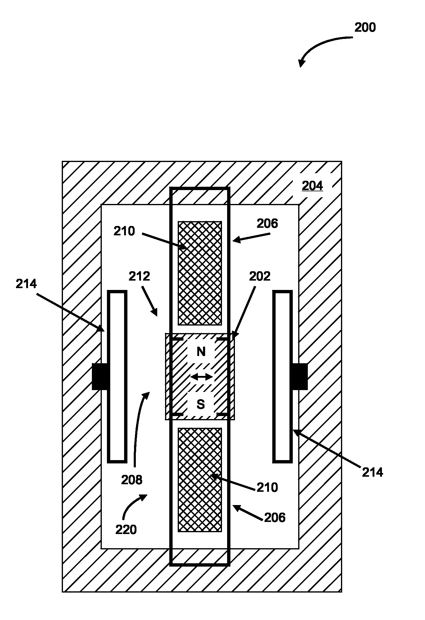
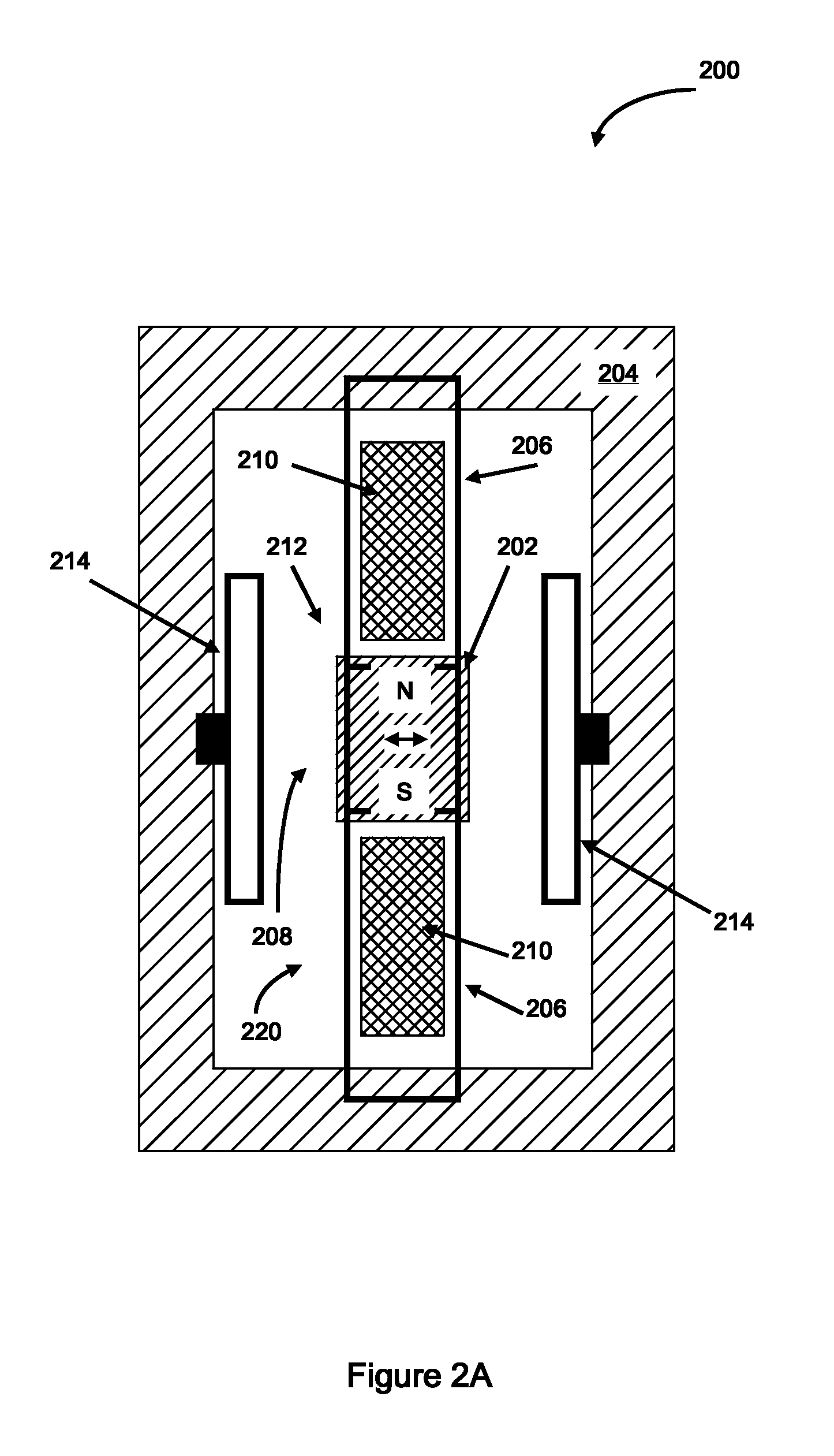
[0036]FIG. 2A is a schematic plan view illustration of an apparatus 200 for converting mechanical vibrations into electrical energy, according to the present invention. A magnet 202 is connected to a frame 204 by a coupling206 which serves to align and guide the magnet 202 disposed within a gap 208 in a ferromagnetic circuit 220. The north “N” and south “S” poles of the magnet 202 are aligned with the pickup portions 210 of the ferromagnetic circuit 220. In this particular embodiment, the ferromagnetic circuit 220 (e.g. yoke, core and pickups) is arranged perpendicular (i.e. extends into and out of the plane of the illustration) to the plane defined by the frame 204. An electrically conductive coil (not shown) can be wrapped around the core, lying above (or below) the plane of the illustration. Coupling 206 is illustrated as a structure comprising flexible, “springs” which serve to allow motion of the magnet 202 to occur substantially in the Z-direction as indicated by the double ar...

third embodiment

[0042]FIG. 3 is a schematic plan view illustration of an apparatus 300 for converting mechanical vibrations into electrical energy, according to the present invention. In this embodiment, the ferromagnetic circuit 330 comprises one or more arms, e.g. 320 and 322, wherein each arm can have an electrically conductive coil 324 and 326 wrapped around the core portion of the corresponding arm of the ferromagnetic circuit 330. It can also be convenient to arrange the arms 320 and 322 in the planar configuration shown, to reduce the overall “height” or volume of the apparatus 300. The remaining elements, magnet 302, coupling 306, frame 304, gap 308, restrainer 314 and their function, are as described above. In the illustrated configuration, the motion of the magnet 302 can be constrained to occur substantially in the plane defined by ferromagnetic circuit 330.

[0043]The following exemplary embodiment of a “Hi-μr Core” VDRG comprises MEM components arranged in a single-magnet, single-core co...


PUM


Abstract

Electromechanical devices that generate an electrical signal in response to an external source of mechanical vibrations can operate as a sensor of vibrations and as an energy harvester for converting mechanical vibration to electrical energy. The devices incorporate a magnet that is movable through a gap in a ferromagnetic circuit, wherein a coil is wound around a portion of the ferromagnetic circuit. A flexible coupling is used to attach the magnet to a frame for providing alignment of the magnet as it moves or oscillates through the gap in the ferromagnetic circuit. The motion of the magnet can be constrained to occur within a substantially linear range of magnetostatic force that develops due to the motion of the magnet. The devices can have ferromagnetic circuits with multiple arms, an array of magnets having alternating polarity and, encompass micro-electromechanical (MEM) devices.

Description

STATEMENT REGARDING FEDERALLY SPONSORED RESEARCH OR DEVELOPMENT[0001]The United States Government has certain rights in this invention pursuant to Department of Energy Contract No. DE-AC04-94AL85000 with Sandia Corporation.FIELD OF THE INVENTION[0002]The invention generally relates to methods and apparatus for generating an electrical signal in response to an external source of mechanical vibrations. Embodiments of the invention operate to convert mechanical energy in the form of vibrations into electrical energy, and can operate as sensors and converters of mechanical to electrical energy. The invention additionally relates to vibration-based energy harvesters and furthermore to velocity damped resonant generators (i.e. VDRGs). Embodiments of the invention can be fabricated as micro-electromechanical (MEM) devices.BACKGROUND OF THE INVENTION[0003]As wireless computing and distributed sensor networks become more mature and widespread, a bottleneck for the technology deployment becom...

Claims


Application Information

Patent Timeline
Patent Type & Authority Patents(United States)
IPC IPC(8): H02K35/00
CPCH02K35/02
Inventor KELLOGG, RICK ALLENBROTZ, JAY KRISTOFFER
Owner NAT TECH & ENG SOLUTIONS OF SANDIA LLC
Why Eureka
Try Eureka