Variable-focus lens and method of manufacturing the same

a lens and variable-focus technology, applied in the field of variable-focus lenses, can solve the problems of optical distortion, change in the shape of the lens housing, and fracture of the transparent plate, and achieve the effects of limiting the variation in the internal pressure of the lens, avoiding optical distortion, and ensuring the rigidity of the lens structur

Active Publication Date: 2009-03-03
INVENIOS FRANCE SAS
View PDF31 Cites 24 Cited by
  • Summary
  • Abstract
  • Description
  • Claims
  • Application Information

AI Technical Summary

Benefits of technology

[0011]One object of the present invention is to provide a variable-focus lens that is easy to manufacture and that makes it possible to limit the variation in the internal pressure of the lens when there is a temperature change, while keeping the structure of the lens rigid.

Problems solved by technology

Excessive pressure of the liquids contained in the housing increases the risk of causing the transparent plates to deform, resulting in an undesirable optical distortion.
In the worst case, if the increase in pressure of the liquids is too high, this may result in fracture of the transparent plates.
One possible limitation of such a lens is that a certain degree of deformation of the corrugated portions 23, 36 may result in a change in the shape of the lens housing, especially the distance separating the two transparent plates 24, 38.
This may lead to the appearance of additional optical defects.
Furthermore, the fact that the housing is deformable may make it difficult for the components of the housing to be precisely positioned, one with respect to another.
Thus, it may prove difficult to keep the optical part of the lens centered with respect to a reference external to the lens.
In addition, the production of the “S”-shaped portions 23, 36 requires specific stamping steps, which complicates the manufacture of such a lens.

Method used


Image

  • Variable-focus lens and method of manufacturing the same
  • Variable-focus lens and method of manufacturing the same
  • Variable-focus lens and method of manufacturing the same

Examples


Embodiment Construction

[0026]For the sake of clarity, identical elements have been denoted by the same reference numerals in the various figures.

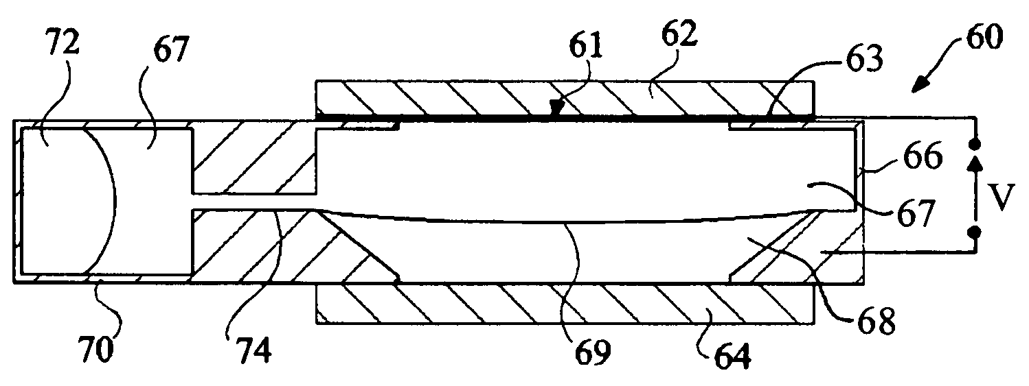
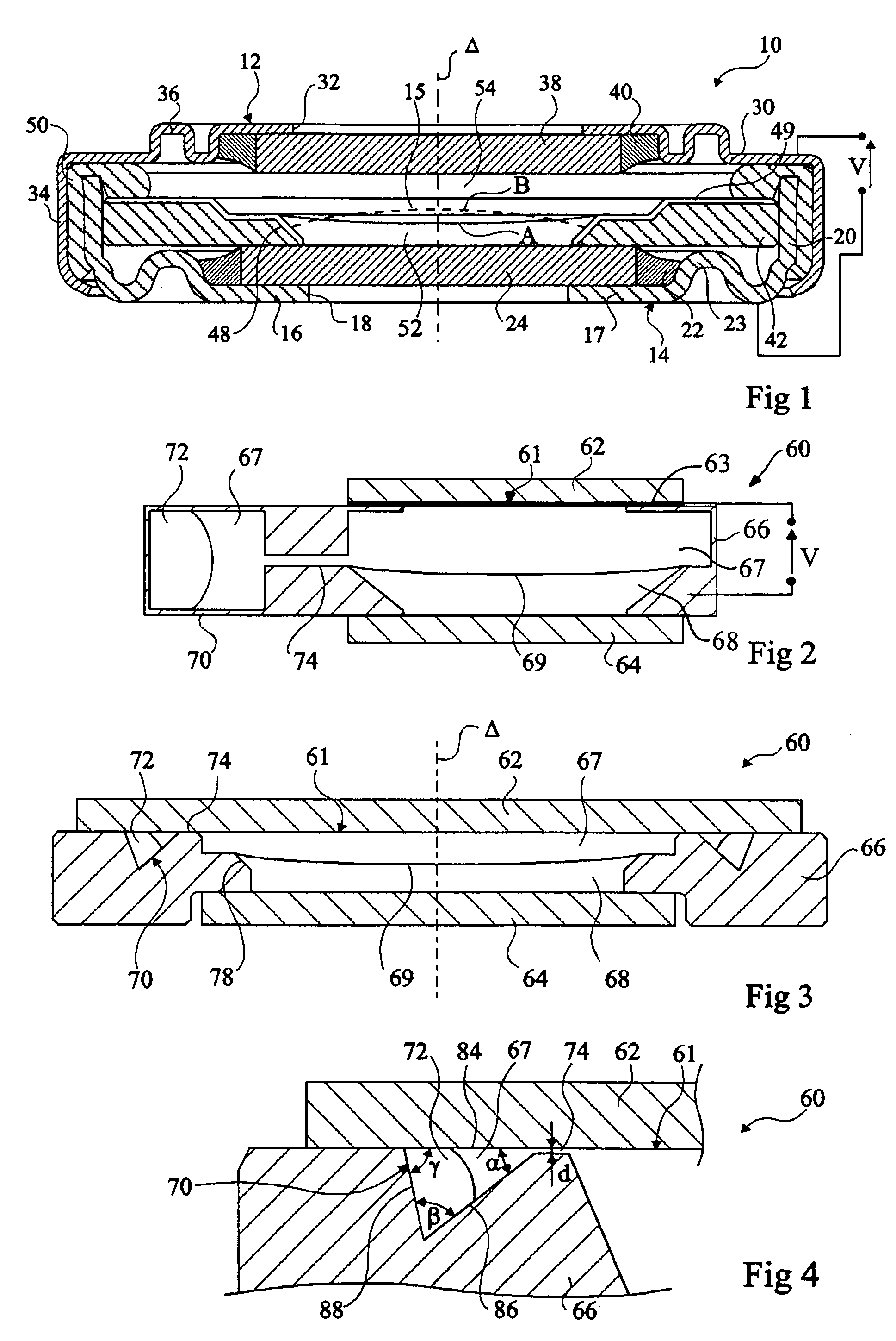
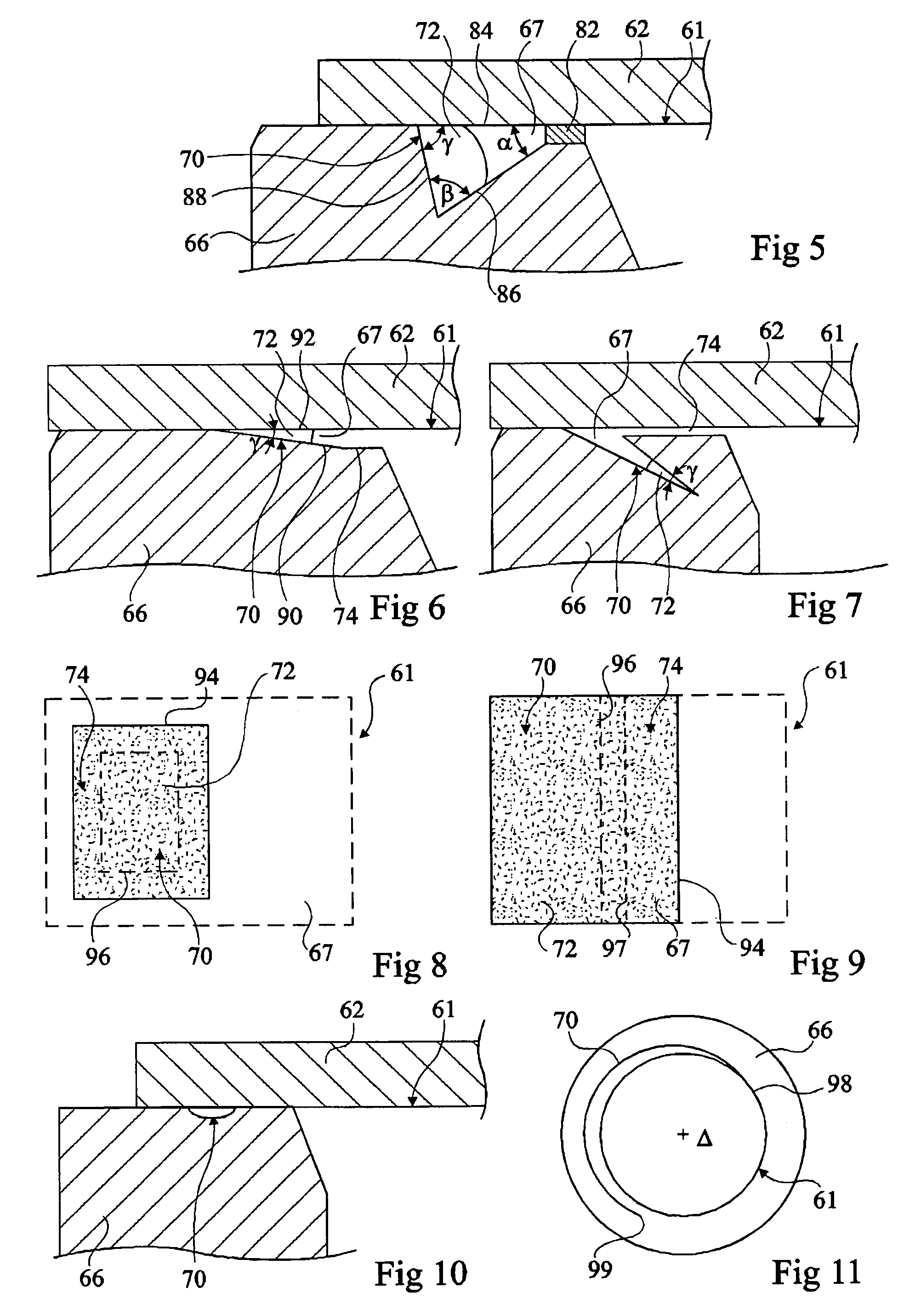
[0027]The present invention relates to intentionally introducing a volume of gas into contact with one of the liquids contained in the lens, taking care to prevent the volume of gas from being present in the region through which the light rays pass. Retention measures are used to prevent the volume of gas from being displaced into the light path. When the temperature changes, the liquids contained in the lens expand, and this expansion is compensated by the volume of gas, which by nature is very compressible, thus limiting the change in internal pressure of the lens. The gas may be, for example, air, an inert gas or a mixture of inert gases, or, alternatively or in combination, the vapour of one of the liquids contained in the lens.

[0028]According to the invention, the volume of gas could comprise, for example, one or more bubbles of gas contained in the lens.

[00...


PUM


Abstract

The invention relates to a variable-focus lens (60) for focusing light rays in light paths passing through the lens along an optical axis (Δ). The lens comprises an arrangement of first and second immiscible liquids (67, 68) that have different refractive indices and are in contact over a moveable refractive optical interface (69), a volume of gas (72) in contact with one of said liquids, and a retention measure (70, 74) for keeping the volume of gas away from the light paths of the light rays passing through the lens for focusing.

Description

CROSS-REFERENCE TO RELATED PATENT APPLICATIONS[0001]The right of foreign priority is claimed under 35 U.S.C. §119(a) based on France Application No. 0551737, filed Jun. 23, 2005, the entire contents of which, including the specification, drawings, claims and abstract, are incorporated herein by reference.BACKGROUND OF THE INVENTION[0002]The present invention relates to a variable-focus lens and more particularly to a lens involving the deformation of a body of liquid (“drop”) by electrowetting effects.[0003]A variable-focus lens usually comprises an enclosure, bounded by two transparent windows, which contains at least two immiscible liquids of different refractive indices. The two liquids are in contact over a moveable refractive interface through which the light rays received by the lens pass. The liquid lens includes a system for deforming the moveable refractive interface by electrowetting effects, thus making it possible to modify the optical power of the lens.[0004]The housing...

Claims


Application Information

Patent Timeline
Patent Type & Authority Patents(United States)
IPC IPC(8): G02B1/06G02B3/12
CPCG02B3/14G02B7/008G02B26/005G02B3/12
Inventor BERGE, BRUNOPESEUX, JEROMEMAILLARD, MATHIEUCRAEN, PIERRE
Owner INVENIOS FRANCE SAS
Why Eureka
Try Eureka