Vehicle with a catadioptric camera

a catadioptric camera and camera body technology, applied in the field of vehicles with catadioptric cameras, can solve problems such as spatial monitoring systems, and achieve the effect of improving spatial monitoring

Inactive Publication Date: 2009-03-03
DAIMLER AG
View PDF15 Cites 3 Cited by
  • Summary
  • Abstract
  • Description
  • Claims
  • Application Information

AI Technical Summary

Benefits of technology

[0008]It is an object of the present invention to provide a vehicle which has at least one catadioptric camera fitted on the vehicle, and which ensures improved spatial monitoring.
[0009]Accordingly, the invention relates to a vehicle with at least one catadioptric camera fitted on the vehicle, which has an optical axis and at least a first mirror arranged on the optical axis. The optical axis is inclined with respect to a vertical. This has the advantage that the camera can also observe spatial regions in the immediate vicinity of the vehicle, in particular road surfaces, which would lie in the blind regions of the camera if its optical axis was arranged vertically. The oblique setting is preferably selected so that the vehicle completely fills up one of the blind regions.
[0011]The semivertex angle of the cone forming the second blind region, or lower blind region, is denoted by χ. This blind region is generally filled at least partially by the vehicle itself. According to the invention, this semivertex angle χ is preferably greater than the angle α. This prevents the camera from detecting unnecessarily large areas of the vehicle which are generally not of interest to be observed.
[0013]A catadioptric camera is preferably mounted on the nose and / or the rear of the vehicle. This makes it possible to monitor the space at the back and front of the vehicle. This is important especially when parking the vehicle. The catadioptric camera may in this case be mounted on the engine hood, on the trunk door, on the fenders or on the bodywork above the fenders.
[0014]If the angles α, β and χ are selected as indicated, then both the fender of the vehicle and a horizontal lie in the field of view of the catadioptric camera, which is mounted on the nose or rear of the vehicle. This allows optimal monitoring of the environment of a vehicle, especially when the space in front of or behind the vehicle needs to be monitored for parking.

Problems solved by technology

Since the blind regions of a catadioptric camera cannot be made arbitrarily small, there are regions in the immediate vicinity of the vehicle which cannot be seen by these known spatial monitoring systems.

Method used


Image

  • Vehicle with a catadioptric camera
  • Vehicle with a catadioptric camera
  • Vehicle with a catadioptric camera

Examples


Embodiment Construction

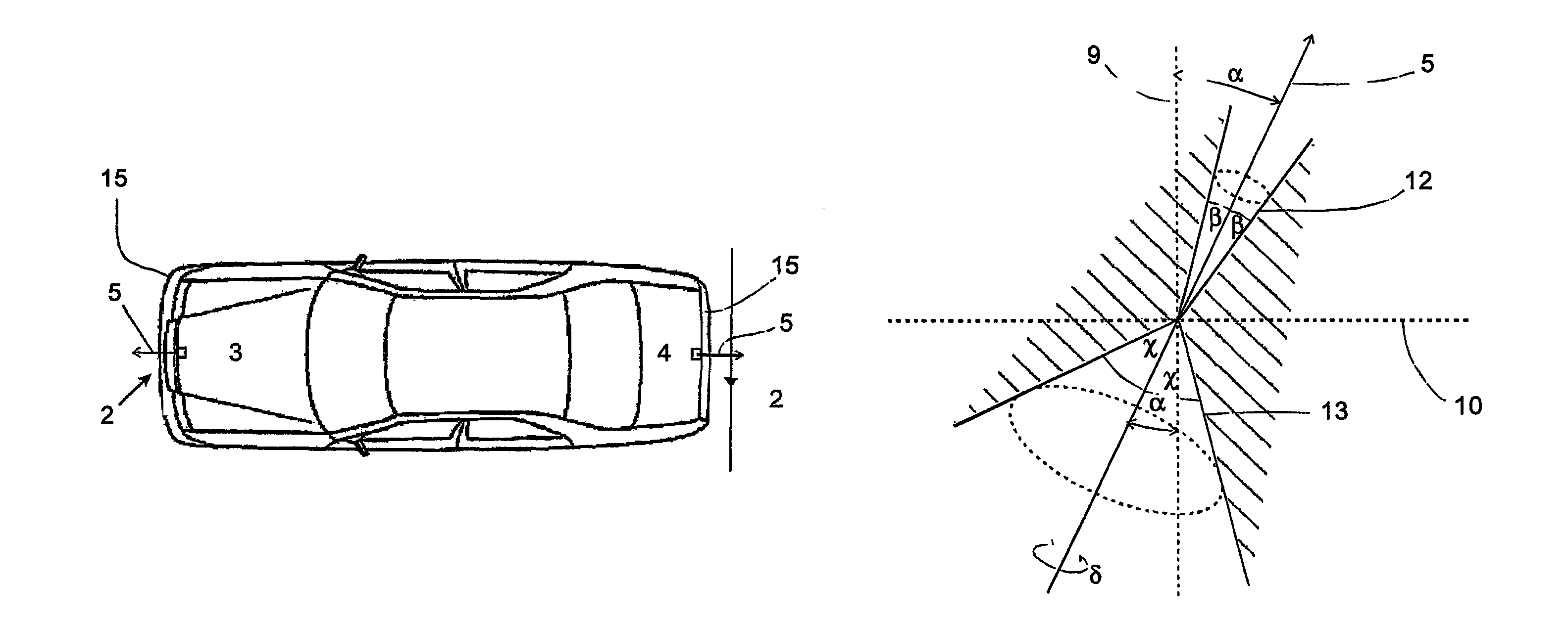
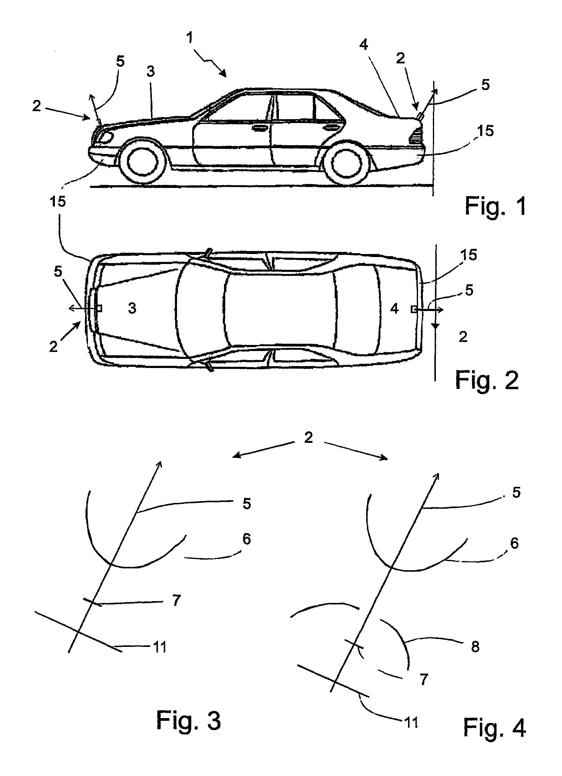
[0024]FIGS. 1 and 2 shows a side view and a plan view of a configuration of a vehicle 1 according to the invention, with an engine hood 3, a trunk door 4 and fenders 15. The vehicle 1 has two catadioptric cameras 2. One of the cameras 2 is mounted on the engine hood 3 of the vehicle, and the other camera 2 is mounted on the trunk door 4 of the vehicle, both in a position near the edge. The cameras may, however, also be fitted on the fenders 15. The cameras 2 respectively have an optical axis 5. The pictures delivered by the cameras 2 are processed, and an image resulting from this is provided to the driver of the vehicle 1 via a screen device (not shown). The pictures delivered by the cameras 2 may, however, also be used to automatically determine the distance of the vehicle 1 from neighboring vehicles or obstacles, for example with the aid of a suitably programmed microprocessor.

[0025]The vehicle 1 furthermore has devices (not shown) for retracting and deploying the camera 2. When ...


PUM


Abstract

The invention relates to a vehicle (1) comprising at least one catadioptric camera (2), which is mounted on the vehicle and which has an optical axis (5) and at least one first mirror (6) that is arranged on the optical axis. The optical axis (5) of the camera (2) is slanted relative to a vertical (9).

Description

CROSS REFERENCE TO RELATED APPLICATION[0001]This application is a national stage of PCT / EP2004 / 000349 filed Jan. 19, 2004 and based upon DE 103 03 013.1 filed Jan. 27, 2003 under the International Convention.BACKGROUND OF THE INVENTION[0002]1. Field of the invention[0003]The present invention relates to a vehicle with at least one catadioptric camera fitted on the vehicle. The camera is one in which at least one curved mirror arranged on the optical axis of the camera is used as an imaging element. The camera allows panoramic viewing in directions transverse to the optical axis, with an azimuth angle of up to 360° with respect to the latter. According to the invention, the catadioptric camera is preferably used to monitor the space at the back and front of the vehicle.[0004]2. Related Art of the Invention[0005]Along the optical axis, the field of view of a catadioptric camera is bounded in both directions by conical blind regions. The field of view boundary of such a cone, or its se...

Claims


Application Information

Patent Timeline
Patent Type & Authority Patents(United States)
IPC IPC(8): G03B17/48B60Q1/00B60Q1/48G08G1/14G08G1/16H04N7/18H04N9/47B60R1/00
CPCB60R1/00B60R11/04B60R2300/105B60R2300/30B60R2300/802B60R2300/806B60R2300/8066
Inventor FRANKE, UWEWUERZ-WESSEL, ALEXANDER
Owner DAIMLER AG
Why Eureka
Try Eureka