Transmission and drive train for a vehicle

a technology for transmission and drive train, which is applied in the direction of electric propulsion mounting, transportation and packaging, gearing, etc., can solve the problems of loss of the above-mentioned yaw-torque-free force transmission advantage, disadvantageous inability to start the vehicle, etc., so as to reduce the overall production cost of the vehicle, leave more structural space free, and reduce the effect of the overall production cos

Inactive Publication Date: 2009-03-10
ZF FRIEDRICHSHAFEN AG
View PDF24 Cites 26 Cited by
  • Summary
  • Abstract
  • Description
  • Claims
  • Application Information

AI Technical Summary

Benefits of technology

[0012]The transmission according to the invention is a system of simple design with small overall dimensions, which can be made inexpensively and also takes up little structural space.
[0013]This is achieved by the feature that the two first shafts of the planetary gearsets, which are connected to a drive input shaft, are also connected to one another at least by a gear wheel mounted on the housing. The force input to the transmission, which takes place in the distributor transmission devices known from the prior art by way of a ring gear of large diameter, is provided at most at the outer diameter of the two planetary gearsets in the transmission design. In a simple manner, this reduces the diameter of the transmission, according to the invention, compared with those of distributor transmissions known from current practice, without essentially enlarging the external dimensions of the transmission in the axial direction.
[0016]This provides the advantageous possibility of distributing a drive torque from a drive engine between the two output shafts by way of operating-status-dependent control and regulation of the transmission ratio of the continuously variable ratio device of the active connection with continuously adjustable degrees of distribution between an upper and a lower limit value of a degree of distribution of the drive torque delivered to the transmission.
[0017]With the drive train for a vehicle comprising a power source with at least two driven vehicle axles and at least one transmission according to the invention as described above, which is arranged so as to enable the distribution, as necessary, and in an operating-status-dependent manner, of the drive torque from the power source between the driven vehicle axles in a power path between the power source and the vehicle's axles and / or in a power path of a vehicle axle for the distribution, as necessary, and in an operating-status-dependent manner, of the fraction of the drive torque delivered to the axle in the transverse direction of the vehicle between two drive wheels of the vehicle's axle. The possibility is given, on the one hand, of continuously distributing a drive torque in the longitudinal and / or the transverse direction of the vehicle and, on the other hand, of constructing a vehicle with a structural-space-optimized and inexpensive drive train. In particular, the structural-space-optimized and inexpensive design of the drive train reduces the overall production cost of a vehicle and leaves more structural space free in the area of the drive train, where little structural space is usually available in vehicles, compared with solutions known from current practice.

Problems solved by technology

However, these two advantages are offset by the drawback that because of the equalizing action of a differential, the propulsive forces that can be transferred to the road by two drive wheels of a vehicle axle or from two or more driving axles is determined in each case by the lower or lowest transferable drive torque of the two drive wheels or driving axles.
This means that when, for example, a drive wheel resting on smooth ice skids, no torque higher than that of the skidding drive wheel can be supplied to the other drive wheel, even when the latter is on ground that it could grip.
In such a driving situation, the vehicle might disadvantageously not be able to start off because of the equalizing action of a differential, which allows a difference of speed between two drive output shafts of the differential.
At the same time, however, the advantage of the above-mentioned yaw-torque-free force transmission is lost and the free adaptation of the wheel rotation speeds to the path lengths of the two driving tracks of the two wheels of a driving axle is also disadvantageously prevented.
However, this all-wheel distributor system, known from the prior art, has the disadvantage that variable torque distribution can only be effected to a limited extent and that its design is elaborate.
Owing to its elaborate design, the all-wheel distributor system has large overall dimensions so the all-wheel distributor system takes up more structural space and has a high inherent weight.

Method used


Image

  • Transmission and drive train for a vehicle
  • Transmission and drive train for a vehicle
  • Transmission and drive train for a vehicle

Examples


Embodiment Construction

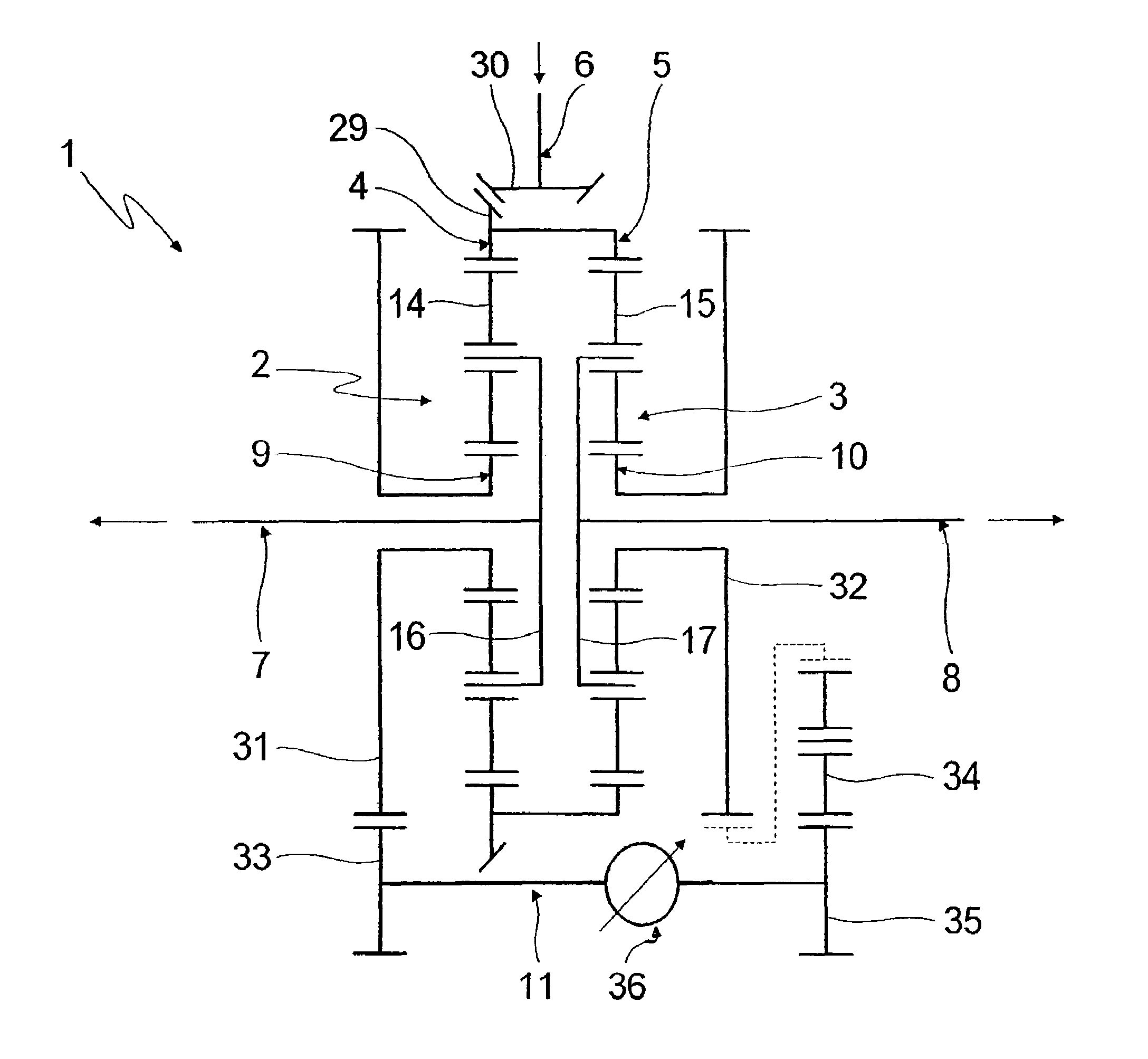
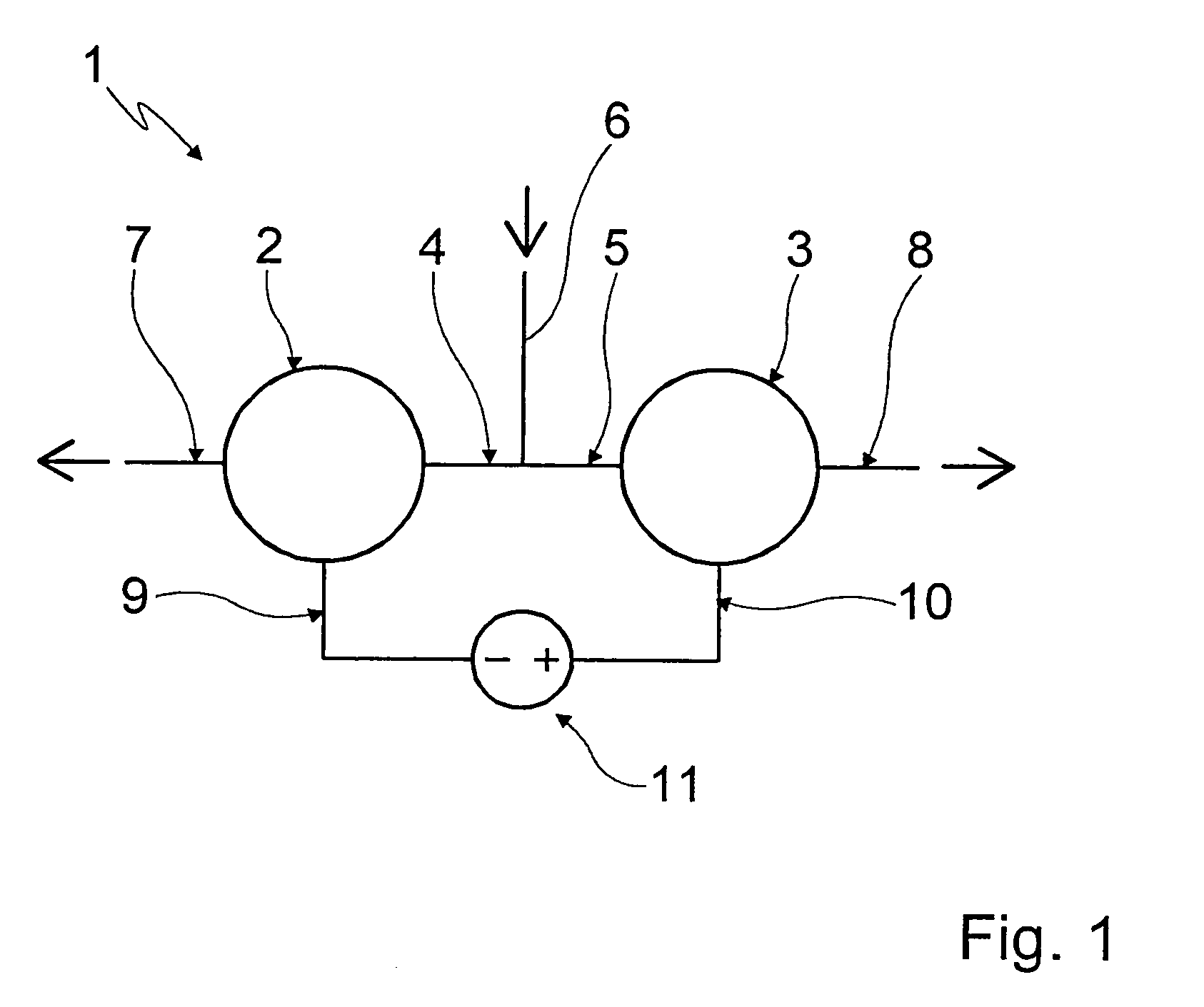
[0034]Referring to FIG. 1, a basic layout of a transmission or transmission device 1 is shown, which can be used as a differential in a power path of a vehicle's drive train between a power source and the driven vehicle axles for the longitudinal distribution of a drive torque from the power source between at least two driven axles, or in a power path of at least one of the driven vehicle axles for the transverse distribution of a fraction of a drive torque delivered to a driven vehicle axle between two drive wheels of that axle.

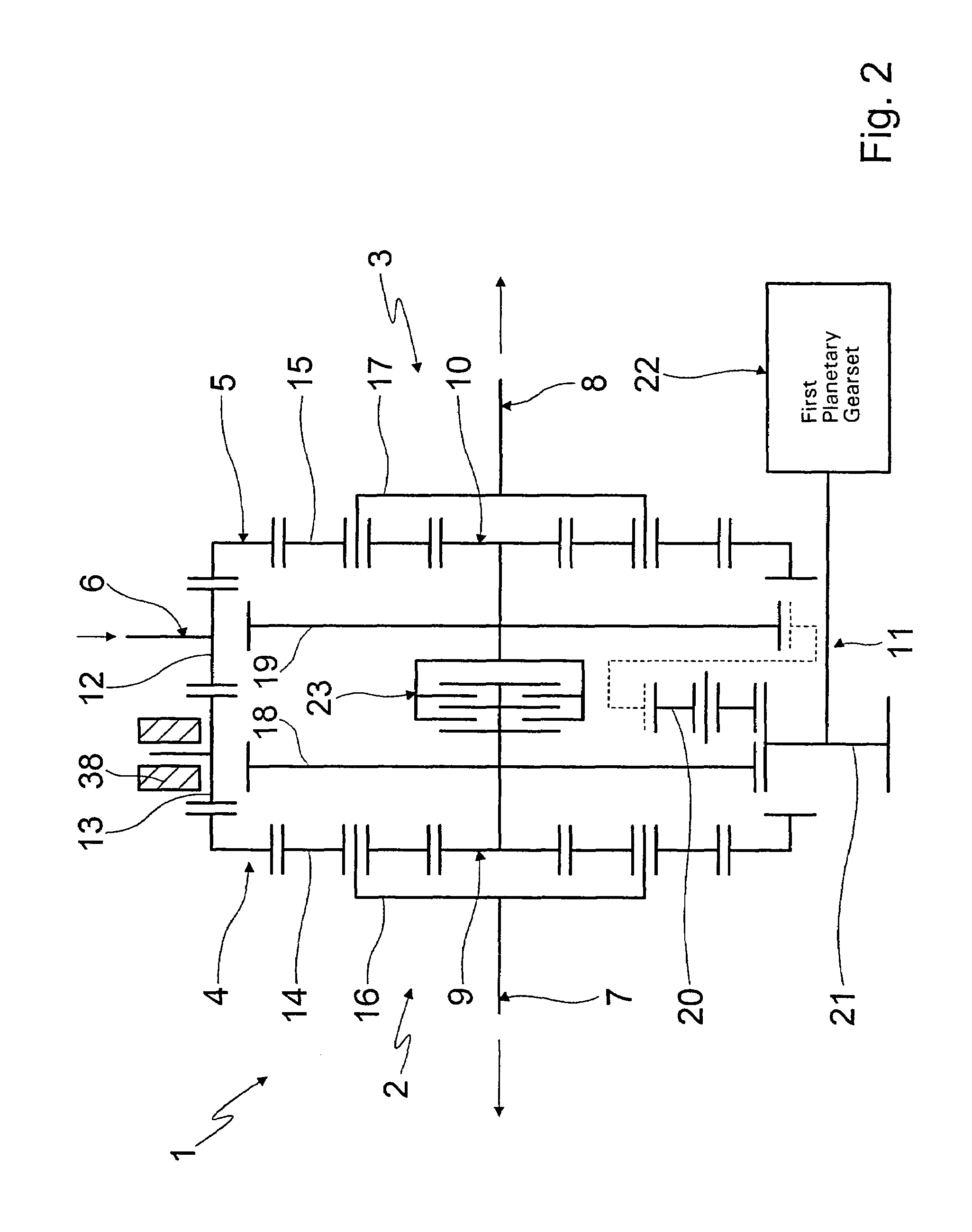
[0035]The transmission 1 is configured with a first planetary gearset 2 and a second planetary gearset 3 which, depending on the respective application concerned, can be made as minus, plus, bevel gear or sequential planetary gearsets. In each case, a first shaft 4, 5 of the two planetary gearsets 2, 3 is connected to a drive input shaft 6, which constitutes a transmission output shaft of a main gearbox (not shown) of the drive train. In each case, second sh...


PUM


Abstract

A transmission for distributing a drive torque to two drive output shafts, with two planetary gearsets each having at least three shafts. A respective shaft of a planetary gearset is connected to a drive input shaft. Furthermore, one shaft of each planetary gearset constitutes one of the output shafts and in each case at least one further shaft of a planetary gearset is connected with a shaft of another planetary gearset. An operation-status-dependent torque of one shaft can be supported by the connection, depending on an operating status of the other shaft connected thereto, in such manner that when there is a rotation speed difference between the output shafts, a speed-difference-changing torque is applied to the planetary gearsets. Furthermore, a drive train is proposed, in which a drive torque from a drive-power-source is distributed variably in the longitudinal and transverse direction of the vehicle in an operation-status-dependent manner.

Description

[0001]This application is a national stage completion of PCT / EP2004 / 011528 filed Oct. 14, 2004 which claims priority from German Application Serial No. 103 48 960.6 filed Oct. 22, 2003.FIELD OF THE INVENTION[0002]The invention concerns a transmission for distributing a drive torque to at least two drive output shafts with at least two planetary gearsets each having at least three shafts and a drive train of a vehicle having a power source, at least two driven vehicle axles and a transmission.BACKGROUND OF THE INVENTION[0003]In vehicles known from prior practice, a drive torque produced by a power source or drive engine is transmitted by a transmission device to the drive wheels of a driven vehicle axle, as necessary. Where vehicles, such as all-wheel passenger cars or all-wheel-drive goods vehicles, are made with more than one driven axle, the power of the engine in the drive train of such a vehicle has to be distributed among the driven vehicle axles.[0004]For this power distributi...

Claims


Application Information

Patent Timeline
Patent Type & Authority Patents(United States)
IPC IPC(8): F16H37/08F16H37/02F16H48/30B60K1/00B60K17/35B60K17/356B60K23/04F16H48/10F16H48/11
CPCB60K17/3505B60K17/356F16H48/11F16H48/10B60K1/00
Inventor BAASCH, DETLEFGUMPOLTSBERGER, GERHARDPELCHEN, CHRISTOPHSCHMOHL, BARBARAMAIR, ULRICHROSEMEIER, THOMAS
Owner ZF FRIEDRICHSHAFEN AG
Why Eureka
Try Eureka