Method and device for visually supporting an electrophysiological catheter application

a technology of electrophysiological catheter and visual support, which is applied in the direction of catheter, application, angiography, etc., can solve the problem that the user is not usually able to accurately capture the relationship between the displayed 3d mapping data, and achieve the effect of avoiding inaccuracy

Active Publication Date: 2009-03-10
SIEMENS HEALTHCARE GMBH
View PDF27 Cites 20 Cited by
  • Summary
  • Abstract
  • Description
  • Claims
  • Application Information

AI Technical Summary

Benefits of technology

[0012]By registering the recorded 2D fluoroscopy images with the 3D mapping data, and displaying them together, from the same perspective, the relationship between the two images can immediately be seen by the electrophysiologist. This is certainly true if 3D mapping data is displayed separately alongside the corresponding 2D fluoroscopy images on a separate display, but is even more so, however, if the two images are displayed superimposed, as this enables the observer to see immediately which areas are not yet sufficiently recorded with the mapping system. A further advantage of the present invention is that the 2D fluoroscopy images also show the relevant current positions of all catheters and components located in them.
[0013]In one embodiment of the invention, the same display perspective may be achieved for a predefined position of the x-ray image recording system or a predefined 2D fluoroscopy image, by rotating the display of the 3D mapping data so that it shows the same perspective. In an alternative embodiment, the display is selected by the operator by interactively rotating the 3D mapping data, and the image recording system is controlled so that a 2D fluoroscopy image is thus recorded from the same perspective. The 3D mapping data and the 2D fluoroscopy images are therefore preferably recorded in the same phase of the cardiac cycle, to avoid inaccuracies as a result of cardiac movement. This synchronization with regard to the cardiac cycle phase can be achieved by timing the image recording system and the mapping system by means of the same ECG trigger unit.
[0014]The device for implementing this method therefore comprises one or more interfaces for input of the 3D mapping data and the image data from the 2D fluoroscopy images, a registration module for registering the 2D fluoroscopy images with the 3D mapping data, and, connected to the registration module, a display module that simultaneously displays the output data of the 3D mapping data, side-by-side or superimposed, with the corresponding 2D fluoroscopy image, from the same perspective, so that it can be viewed on a display unit, in particular a monitor. The device may therefore be configured as a component of the mapping system or of the image recording system, or even as a standalone device.

Problems solved by technology

Even the orientation to the displayed 3D mapping data does not guarantee that the ventricle surface generated from this data corresponds exactly to the anatomical conditions, since this would require the endocardial surface to be mapped very closely on a point-by-point basis.
The additional anatomical image information of the 2D fluoroscopy images is still available during the mapping procedure, but can only be used to a limited extent—if at all—since the operation of the mapping system demands the electrophysiologist's undivided attention, so that he or she is not usually able to accurately capture the relationship between the displayed 3D mapping data and the simultaneously displayed 2D fluoroscopy image.
The acquisition of 3D mapping data therefore often results in the generation of a surface of the endocard in the ventricle to be treated, which only approximately corresponds to the actual anatomy of the ventricle, because anatomically relevant surface points of the endocard are not sufficiently mapped.
Furthermore, for reasons of cost and practicality, in many cases only the ablation catheter with the position sensors is displayed relative to the mapped endocard surface on the EP mapping system monitor.
Furthermore, even this method only allows the catheter carrying the corresponding position sensors to be displayed on the screen.

Method used


Image

  • Method and device for visually supporting an electrophysiological catheter application
  • Method and device for visually supporting an electrophysiological catheter application
  • Method and device for visually supporting an electrophysiological catheter application

Examples


Embodiment Construction

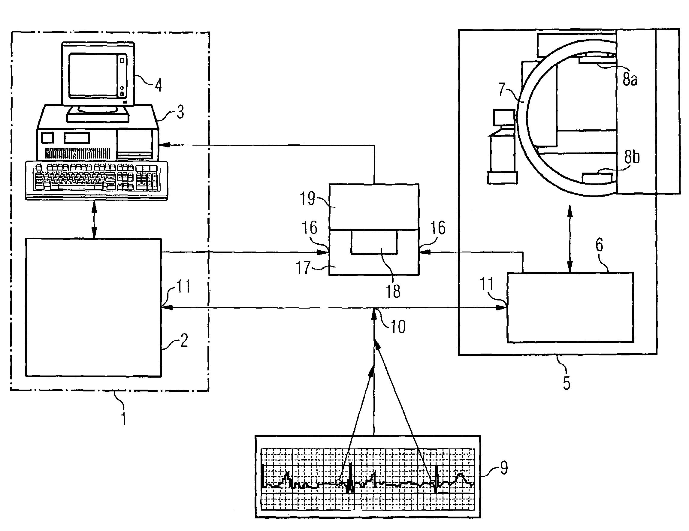
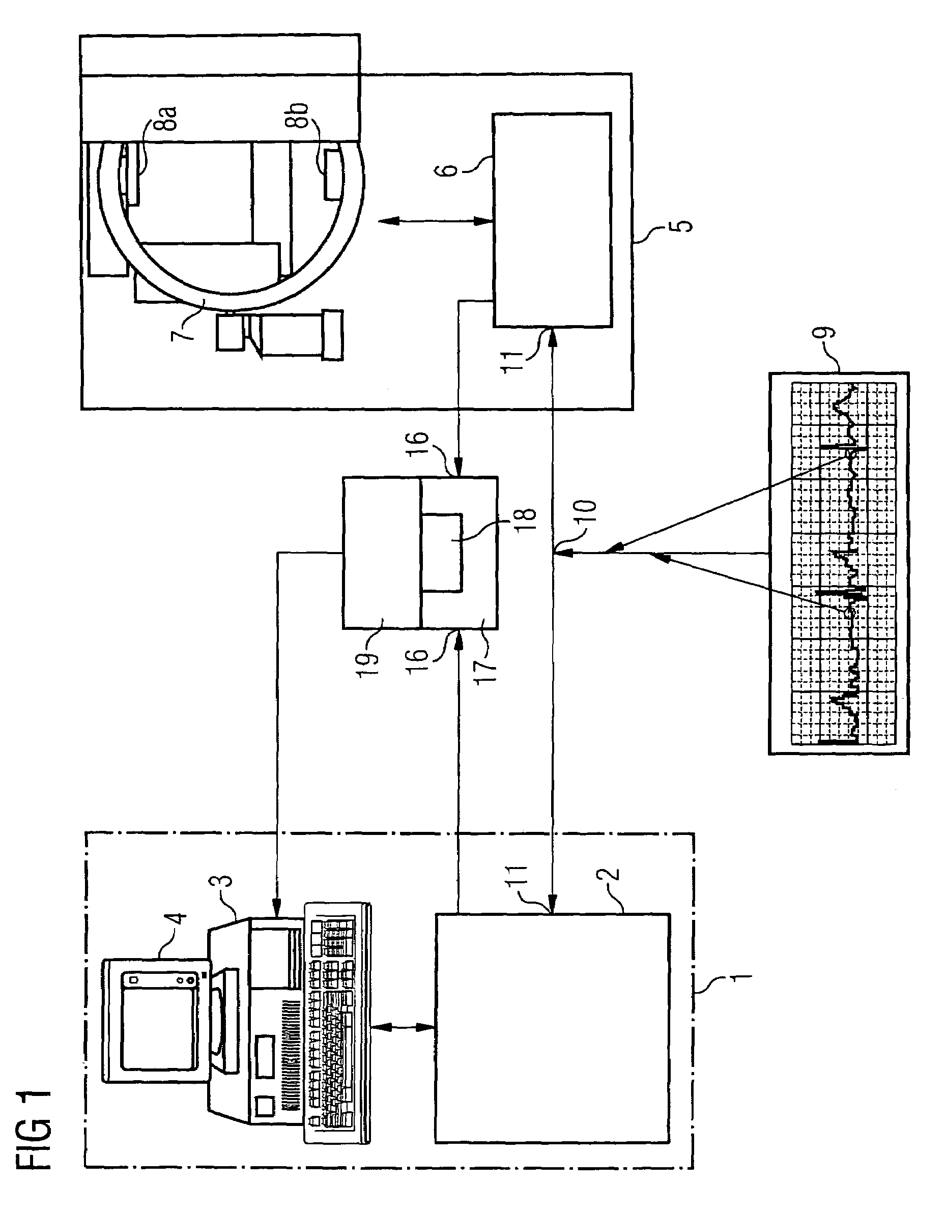
[0023]FIG. 1 schematically illustrates a part of an EP mapping system 1 with a recording unit 2 for the 3D mapping data, which is connected to an analysis and image-processing unit 3 for displaying the captured data on a screen 4. Furthermore, by way of example, an x-ray system 5 in the form of a C-arm system is shown, said x-ray system having an image system 6 for providing the 2D fluoroscopy images. The C-arm system 5 comprises the C-arm 7, an x-ray source 8a, and x-ray detector 8b. In the known method, the C-arm 7 is designed such that it can be rotated about several axes. In this example an ECG is recorded from the patient, by means of an ECT recording system 9, during the catheter application. The ECG recording system 9 has a trigger output 10, which is connected to corresponding trigger inputs 11 on the image system 6 of the x-ray system 5 and to the recording unit 2 of the EP mapping system 1. This ECG triggering enables both the 3D mapping data and the 2D fluoroscopy images ...


PUM


Abstract

The present invention relates to a method for visually supporting an electrophysiological catheter application in the heart, in which, during the execution of the catheter application, 2D fluoroscopy images (13) of the area of the heart being treated are recorded with an x-ray image recording system (5) and displayed together with 3D mapping data (14) of the area being treated, said 3D mapping data having been prepared simultaneously. A feature of this method is that the 2D fluoroscopy images (13) are registered with the 3D mapping data (14), and said 3D mapping data (14) is displayed, from the same perspective as the 2D fluoroscopy images (13), alongside said 2D fluoroscopy images (13) or image content derived from these (14), or is superimposed over them in the display.

Description

CROSS REFERENCE TO RELATED APPLICATIONS[0001]This application claims priority to the German application No. 10 2004 020 587.6, filed Apr. 27, 2004 which is incorporated by reference herein in its entirety.FIELD OF INVENTION[0002]The present invention relates to a method for visually supporting an electrophysiological catheter application in the heart, in which, during the execution of the catheter application, 2D fluoroscopy images of the area of the heart being treated are recorded with an x-ray image recording system and displayed together with electroanatomical 3D mapping data of the area being treated, said 3-D mapping data having been prepared simultaneously. The invention also relates to a device for implementing this method.BACKGROUND OF INVENTION[0003]The treatment of cardiac dysrhythmias has changed significantly since the introduction of the technique for catheter ablation by means of high-frequency current. In this technique an ablation catheter is introduced under x-ray ...

Claims


Application Information

Patent Timeline
Patent Type & Authority Patents(United States)
IPC IPC(8): A61B5/05A61B19/00A61B5/042A61B6/00A61B6/02A61B6/12A61B18/00A61M25/095
CPCA61B5/0422A61B6/4441A61B6/503A61B6/584A61B6/5235A61B6/5247A61B6/02A61B19/5244A61B2019/5289A61B6/504A61B34/20A61B2090/364A61B5/7425A61B5/287
Inventor BOESE, JANRAHN, NORBERT
Owner SIEMENS HEALTHCARE GMBH
Why Eureka
Try Eureka